A helmet printing device

A technology for printing devices and safety helmets, which is applied in printing, printing machines, rotary printing machines, etc., can solve the problems of poor printing effect, cumbersomeness, and affecting the printing quality of helmet characters and patterns, so as to improve printing effect and quality, avoid wasteful effect

Active Publication Date: 2021-12-24
陈余
View PDF5 Cites 0 Cited by
  • Summary
  • Abstract
  • Description
  • Claims
  • Application Information

AI Technical Summary

Problems solved by technology

[0003] In order to overcome the shortcomings of the existing helmet printing technology equipment, which are complicated and cumbersome to use, the printing effect is poor, and the printing quality of helmet characters and patterns is affected, the technical problem is to provide a method that can evenly smear the ink to ensure the printing effect and quality. , a hard hat printing device that is easy to operate and has high printing efficiency

Method used


Image

  • A helmet printing device
  • A helmet printing device
  • A helmet printing device

Examples


Embodiment 1

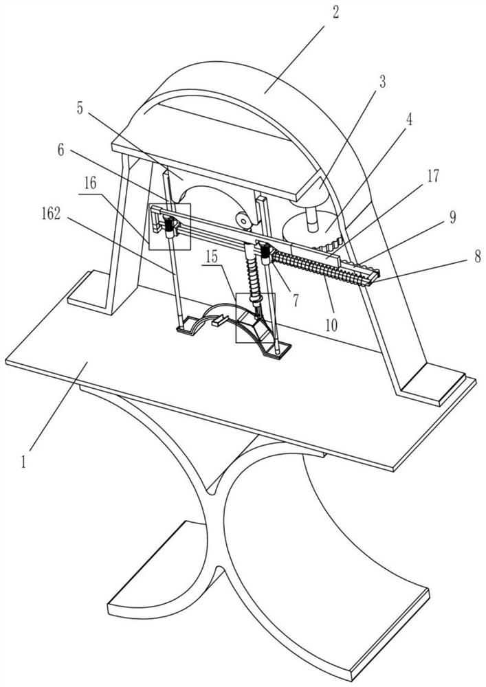
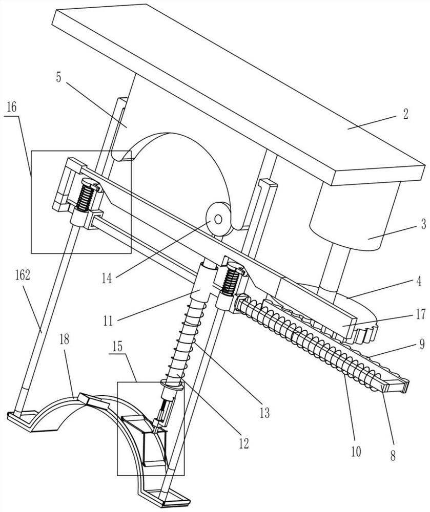
[0021] A kind of safety helmet printing device, refer to figure 1 and figure 2 As shown, it includes a frame 1, a mounting plate 2, a motor 3, a gear 4, an arc plate 5, a vertical arm 6, a fixed sliding sleeve 7, a lateral movable rod 8, a rack 9, an elastic part 10, a cylindrical Sliding sleeve 11, cylindrical movable rod 12, elastic part two 13, extruding small wheel 14, inking mechanism 15, extruding mechanism 16, extruding plate 17 and printing module 18, described frame 1 is provided with mounting plate 2. A motor 3 is installed on the right side of the bottom side of the installation plate 2, a gear 4 is arranged on the output shaft of the motor 3 through a rotating shaft, and an arc-shaped plate 5 is arranged on the middle part of the bottom side of the installation plate 2. Two vertical arms 6 are fixedly installed in the middle of both sides of the arc-shaped plate 5, and two fixed sliding sleeves 7 are fixedly installed at the bottom ends of the two vertical arms 6...

Embodiment 2

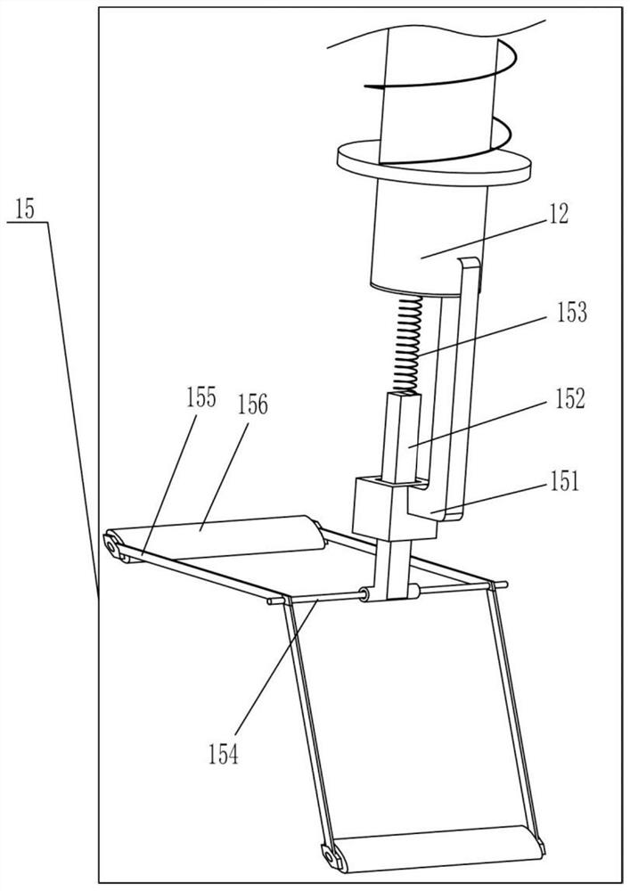
[0026] refer to image 3 As shown, the main difference between this embodiment and Embodiment 1 is that in this embodiment, the ink application mechanism 15 includes a connecting arm 151, a guide rod 152, an elastic member 3 153, a rotating rod 154, a mounting rod 155 and a coating wheel 156, the right side of the lower end of the cylindrical movable rod 12 is provided with a connecting arm 151, and the middle part of the bottom end of the cylindrical movable rod 12 is provided with an elastic member 3 153, and in this embodiment the elastic member 3 153 is the first Two return springs, the bottom end of the connecting arm 151 is provided with a guide hole and a guide rod 152 is slidably arranged in the guide hole, and the guide rod 152 can move up and down in the guide hole, and the upper end of the guide rod 152 is in contact with the elastic The third part 153 is connected, the lower end of the guide rod 152 is provided with a round hole and a rotating rod 154 is installed ...


PUM


Abstract

The invention relates to the technical field of safety helmet manufacturing, in particular to a safety helmet printing device. The technical problem of the present invention is to provide a safety helmet printing device that can evenly smear ink, ensure printing effect and quality, and is easy to operate and has high printing efficiency. The technical scheme of the present invention is: a safety helmet printing device, comprising a frame, a mounting plate, a motor, a gear, an arc-shaped plate, a vertical arm, etc.; A motor is installed on one side, a gear is arranged on the output shaft of the motor through the rotating shaft, and an arc plate is arranged on one side of the mounting plate. In the invention, the motor drives the gear to rotate, the gear drives the rack to move to the left, and the horizontal movable rod drives the ink applicator to move to the left through the cylindrical movable rod to evenly smear the ink on the printing module, and the characters and patterns on the printing module will be automatically Printing on the safety helmet, the printing efficiency is high and the printing effect is good.

Description

technical field [0001] The invention relates to the technical field of production of safety helmets, in particular to a printing device for safety helmets. Background technique [0002] Some signs and characters are generally printed on the helmet to explain the source of the helmet or to enhance the advertising effect. The printing of the existing safety helmet requires the operator to place the printing module on the safety helmet, then the operator adds ink to the printing module, and uses the brush cylinder to evenly brush the ink of the printing module, and the ink passes through the module hole of the printing module Brushing onto the helmet, manual printing is slow and inefficient, and the position of each printing will be inconsistent, affecting the quality of production, and there is also the phenomenon of uneven printing. Therefore urgently need to research and develop a kind of ink can be applied evenly, guarantee the effect and the quality of printing, be easy t...

Claims


Application Information

Patent Timeline
Patent Type & Authority Patents(China)
IPC IPC(8): B41F17/30
CPCB41F17/30
Inventor 叶剑锋
Owner 陈余
Why Eureka
Try Eureka