Composite material connecting structure for railway vehicle and forming method

A composite material and connection structure technology, applied in the field of rail vehicles, can solve the problems of the impact of the driver's and passengers' eardrums, affecting the comfort of rail transit vehicles, air pressure fluctuations, etc. excellent effect

Inactive Publication Date: 2020-05-01
CRRC QINGDAO SIFANG CO LTD
View PDF7 Cites 5 Cited by
  • Summary
  • Abstract
  • Description
  • Claims
  • Application Information

AI Technical Summary

Problems solved by technology

[0002] Large pressure fluctuations are likely to occur during the running of rail transit vehicles. When the airtightness of the vehicle is insufficient, the pressure fluctuations outside the vehicle will enter the vehicle and cause air pressure fluctuations, which will impact the eardrums of the drivers and passengers and affect the rail transportation. vehicle comfort

Method used


Image

  • Composite material connecting structure for railway vehicle and forming method
  • Composite material connecting structure for railway vehicle and forming method
  • Composite material connecting structure for railway vehicle and forming method

Examples


Embodiment 1

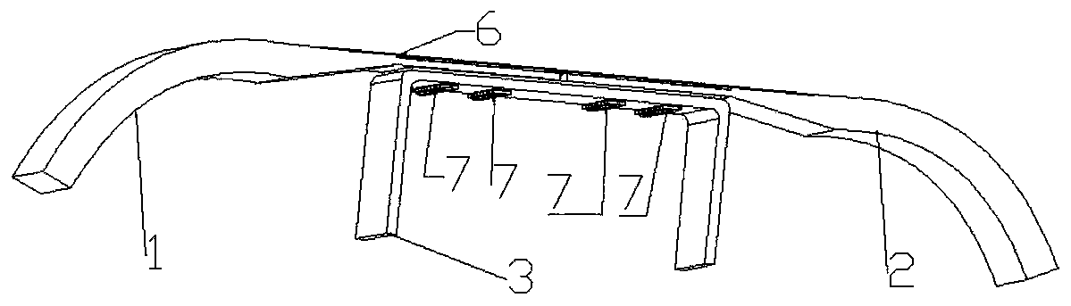
[0079] The first roof skin 1 and the second roof skin 2 are perforated at equal intervals (40 mm) on one side, and the distance between each hole and the edge of the skin is 30 mm. The corresponding positions of the main beam carbon plate 3 and the first roof skin 1 and the second roof skin 2 are equally spaced to punch holes.

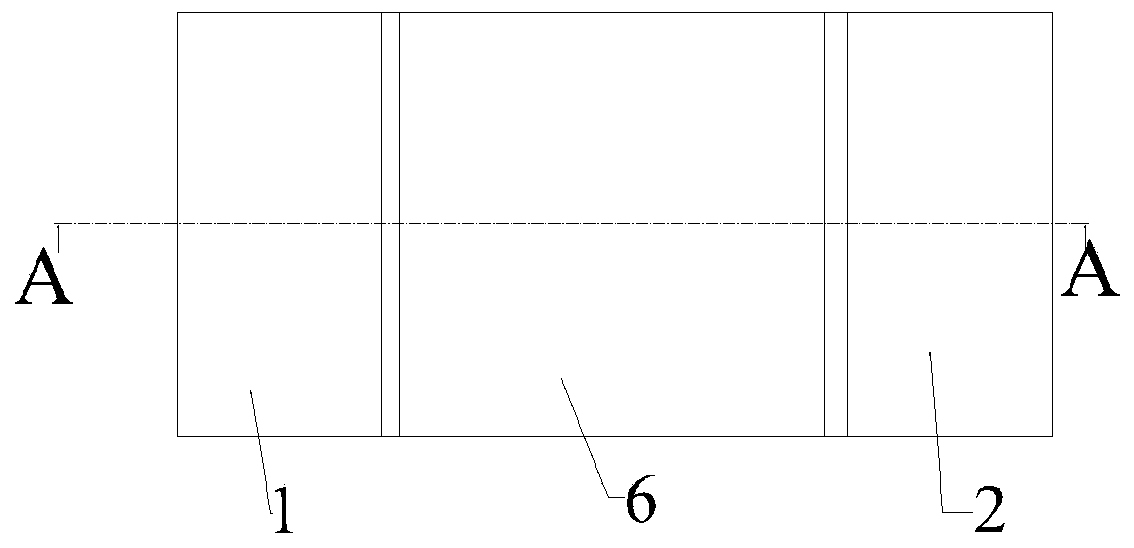
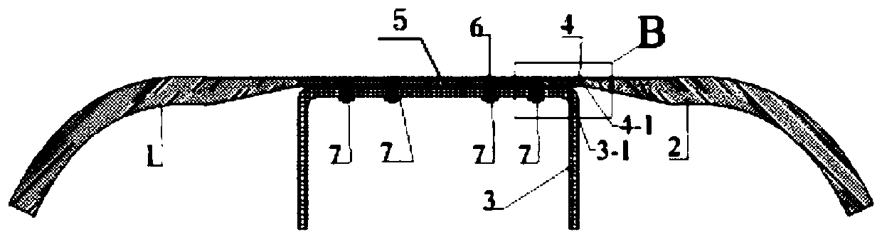
[0080] The main beam carbon plate 3 is located under the first roof skin 1 and the second roof skin 2, and is connected with the first roof skin 1 and the second roof skin 2 by structural glue and rivets. Its placement position is symmetrical to both sides of the splicing gap between the first roof skin 1 and the second roof skin 2 .

[0081] The carbon fiber cover plate 4 is located above the first roof skin 1 and the second roof skin 2 , and is connected with the first roof skin 1 and the second roof skin 2 by means of structural glue. The thickness of the carbon fiber cover plate 4 is 0.3 mm.

[0082] The preparation method comprises the following...

Embodiment 2

[0093] The first roof skin 1 and the second roof skin 2 are perforated at equal intervals (50 mm) on one side, and the distance between each hole and the edge of the skin is 35 mm. The corresponding positions of the main beam carbon plate 3 and the roof skin are equally spaced to punch holes.

[0094] The main beam carbon plate 3 is located under the first roof skin 1 and the second roof skin 2, and is connected with the first roof skin 1 and the second roof skin 2 by structural glue and rivets. Its placement position is symmetrical to both sides of the splicing gap between the first roof skin 1 and the second roof skin 2 .

[0095] The carbon fiber cover plate 4 is located above the first roof skin 1 and the second roof skin 2 , and is connected with the first roof skin 1 and the second roof skin 2 by means of structural glue. The thickness of the carbon fiber cover plate 4 is 0.4mm.

[0096] The preparation method comprises the following steps:

[0097] Step 1: Grinding a...

Embodiment 3

[0107] The first roof skin 1 and the second roof skin 2 are perforated at equal intervals (60 mm) on one side, and the distance between each hole and the edge of the skin is 40 mm. The corresponding positions of the main beam carbon plate 3 and the roof skin are equally spaced to punch holes.

[0108] The main beam carbon plate 3 is located under the first roof skin 1 and the second roof skin 2, and is connected with the first roof skin 1 and the second roof skin 2 by structural glue and rivets. Its placement position is symmetrical to both sides of the splicing gap between the first roof skin 1 and the second roof skin 2 .

[0109] The carbon fiber cover plate 4 is located above the first roof skin 1 and the second roof skin 2 , and is connected with the first roof skin 1 and the second roof skin 2 by means of structural glue. The thickness of the carbon fiber cover plate 4 is 0.5mm.

[0110] The preparation method comprises the following steps:

[0111] Step 1: Grinding a...


PUM

PropertyMeasurementUnit
thicknessaaaaaaaaaa
compressive strengthaaaaaaaaaa
shear strengthaaaaaaaaaa

Abstract

The invention provides a composite material connecting structure for a railway vehicle and a forming method. The structure comprises a first top plate skin, a second top plate skin, a main beam carbonplate and a carbon fiber cover plate, wherein the first top plate skin and the second top plate skin are glued on the top surface of the main beam carbon plate; the first top plate skin is spliced with the second top plate skin; at least one row of holes located in the two sides of the splicing position are formed in the top face of the main beam carbon plate; the first top plate skin is providedwith at least one row of first through holes in one-to-one correspondence with the at least one row of holes in one side; the second top plate skin is provided with two rows of second through holes in one-to-one correspondence with the at least one row of holes in the other side; the first top plate skin and the main beam carbon plate are riveted with the corresponding holes through the first through holes, and the second top plate skin and the main beam carbon plate are riveted with the corresponding holes through the second through holes; and the carbon fiber cover plate is arranged on theouter surface of the splicing position of the first top plate skin and the second top plate skin in an adhesive covering mode. The connecting structure can adapt to connection of rail vehicle composite materials, and the air tightness and the structural strength of connection can be guaranteed.

Description

technical field [0001] The invention relates to the technical field of rail vehicles, in particular to a composite material connection structure and a molding method for rail vehicles. Background technique [0002] Large pressure fluctuations are likely to occur during the running of rail transit vehicles. When the airtightness of the vehicle is insufficient, the pressure fluctuations outside the vehicle will enter the vehicle and cause air pressure fluctuations, which will impact the eardrums of the drivers and passengers and affect the rail transportation. Vehicle comfort. [0003] With the application of composite materials in rail transit vehicles more and more widely, the research on the airtightness of the composite material connection structure in the car body has also become a major focus of the performance assessment of the car body. Contents of the invention [0004] The present invention aims to solve at least one of the technical problems existing in the prior...

Claims


Application Information

Patent Timeline
Patent Type & Authority Applications(China)
IPC IPC(8): B61D17/12B29C70/68B29C70/78B29C65/72B29C65/48B29C65/60B29C65/00
CPCB29C65/48B29C65/601B29C65/72B29C66/02245B29C70/682B29C70/683B29C70/78B61D17/12
Inventor 田爱琴孙琳张联合高玉龙丁叁叁
Owner CRRC QINGDAO SIFANG CO LTD
Why Eureka
Try Eureka