Kitchen waste pretreatment temporary storage tank

A kitchen waste and pretreatment technology, which is applied to containers, fixed filter elements, large containers, etc., can solve the problems of inability to pretreat, reduce the service life of equipment, increase the consumption of manpower and material resources, etc., and achieve proper follow-up Effect of treatment, odor blocking avoidance

Active Publication Date: 2020-05-01
江苏泓润生物质能科技有限公司
View PDF6 Cites 0 Cited by
  • Summary
  • Abstract
  • Description
  • Claims
  • Application Information

AI Technical Summary

Problems solved by technology

[0004] In the existing technology, the treatment of kitchen waste is often purchased by private parties and transported to farms, which not only affects environmental sanitation, but also brings food safety hazards; a small amount of kitchen waste is mixed with domestic garbage and finally disposed of in landfill. Not only has it brought about secondary pollution, but it has also turned kitchen waste into almost useless waste
[0005] With the enhancement of people's awareness of environmental protection and sustainable development, there have been special kitchen waste collection vehicles for kitchen waste collection in the prior art to collect kitchen waste. After recycling, it can be converted into usable resources to achieve energy saving and environmental protection. However, there are still defects in the pretreatment process: 1) It is impossible to pretreat food waste every time it is collected, which will increase the consumption of manpower and material resources. It also prolongs the working time of the equipment and reduces the service life of the equipment; 2) The current state of the temporarily collected kitchen waste cannot be fully understood, so timely and proper follow-up treatment cannot be performed on it

Method used


Image

  • Kitchen waste pretreatment temporary storage tank
  • Kitchen waste pretreatment temporary storage tank
  • Kitchen waste pretreatment temporary storage tank

Examples


Embodiment Construction

[0030] The present invention is described in further detail now in conjunction with accompanying drawing. These drawings are all simplified schematic diagrams, which only illustrate the basic structure of the present invention in a schematic manner, so they only show the configurations related to the present invention.

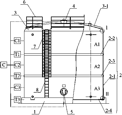
[0031] Such as Figure 1-4 As shown, a temporary storage tank for pretreatment of kitchen waste, the temporary storage tank includes an installation base 1, a temporary storage tank cylinder 2 is fixedly arranged on the upper end of the installation base 1, and a temporary storage tank cylinder 2 is fixed on the upper end of the temporary storage tank cylinder 2 A temporary storage tank cover body 3 is provided, a material inlet 4 is opened on the temporary storage tank cover body 3, a material discharge port 5 is opened at the lower end of the temporary storage tank cylinder body 2, and a fixed setting is provided on the temporary storage tank cover body 3 T...


PUM


Abstract

The invention relates to a kitchen waste pretreatment temporary storage tank. A temporary storage tank cylinder is fixedly arranged at the upper end of a mounting base, a temporary storage tank coveris arranged at the upper end of the temporary storage tank cylinder, a feeding port is formed in the temporary storage tank cover, a discharging port is formed in the lower end of the temporary storage tank cylinder, a fence is fixedly arranged on the temporary storage tank cover, a ladder frame is arranged outside the temporary storage tank cylinder, and a ladder is mounted on the ladder frame. Entering in a next temporary storage cavity can be achieved, and when one of the capacity and the temperature of a third temporary storage cavity at the lowermost position meets the condition, the discharging port is unlocked while the feeding port is locked, so that overflowing is avoided and unexpected opening is avoided when the condition is not met while kitchen waste is temporarily stored, thecurrent state of the kitchen waste is monitored in a layered manner in real time while the kitchen waste is temporarily stored, temperature and capacity parameters of the kitchen waste are mastered in real time, and targeted, timely and proper subsequent treatment of the kitchen waste in different layers is facilitated.

Description

technical field [0001] The invention relates to the technical field of pretreatment of kitchen waste, in particular to a temporary storage pool for pretreatment of kitchen waste. Background technique [0002] With the progress of society and economic development, people's living standards continue to improve, making more and more kitchen waste, whether it can be properly disposed of, will be directly related to food hygiene and safety and the health of the people. [0003] The main characteristics of kitchen waste are high water content, which accounts for 80-90% of the total waste; high organic content, high oil content, high salt content; easy to rot and deteriorate, easy to ferment, easy to stink; easy to breed parasites , eggs and pathogenic microorganisms and mycotoxins and other harmful substances. [0004] In the existing technology, the treatment of kitchen waste is often purchased by private parties and transported to farms, which not only affects environmental san...

Claims


Application Information

Patent Timeline
Patent Type & Authority Applications(China)
IPC IPC(8): B65D88/74B01D29/54B01D29/01
CPCB01D29/01B01D29/54B65D88/744
Inventor 蒋礼兵曹波刘东杨晶歆
Owner 江苏泓润生物质能科技有限公司
Why Eureka
Try Eureka