Eureka AIR delivers breakthrough ideas for toughest innovation challenges, trusted by R&D personnel around the world.

Roller kiln

A roller kiln and furnace technology, applied in the field of heat treatment furnace equipment, can solve the problems of damage to the heating elements and other components at the bottom of the furnace, inconvenient maintenance, poor maintainability, etc., to improve safety and reliability, and reduce contact area , the effect of improving the service life

Pending Publication Date: 2020-05-01
HUNAN JINLU TECH CO LTD
View PDF0 Cites 0 Cited by
  • Summary
  • Abstract
  • Description
  • Claims
  • Application Information

AI Technical Summary

Problems solved by technology

This kind of vault has stable structure, long service life, high strength and strong corrosion resistance, but its maintainability is poor. All refractory bricks lose their supporting structure, which will cause the vault to collapse as a whole), and for some kiln maintenance operations that need to dismantle the vault, it needs to be carried out under the condition of stopping production or even shutting down the furnace, resulting in extremely inconvenient maintenance , and affect production efficiency
At the same time, under the strong corrosion reaction atmosphere of lithium battery materials and other materials, it is inevitable that kiln furniture such as saggers or temperature zone partitions will be damaged during the production process. These damaged kiln furniture exist inside the furnace and are stuck on the transmission roller. If it cannot be taken out in time, the continuous production will be affected at least, and a major safety accident of the arch kiln will occur at the worst.
For the damage of these kiln furniture, usually the roller sticks stuck to the kiln furniture are pulled out to make the kiln furniture fall to the bottom of the furnace, and then the rollers are put on again, and then enter the furnace for cleaning when the furnace is shut down for maintenance. , and the damaged kiln furniture falls to the bottom of the furnace, not only the risk of damaging the heating elements and other components at the bottom of the furnace, but also the subsequent cleaning is extremely inconvenient

Method used


Image

  • Roller kiln
  • Roller kiln
  • Roller kiln

Examples


Embodiment Construction

[0028] The present invention will be described in further detail below in conjunction with the accompanying drawings and specific embodiments.

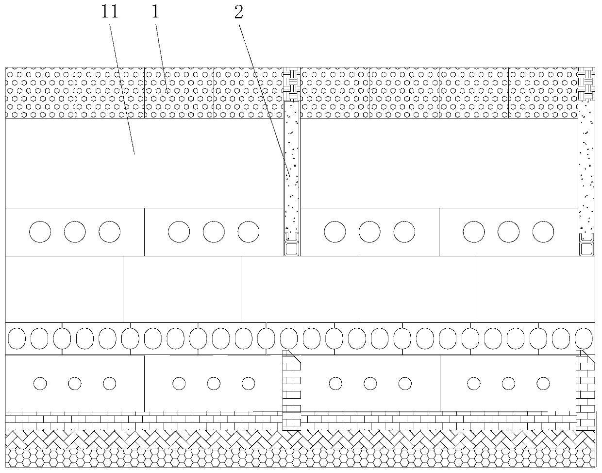
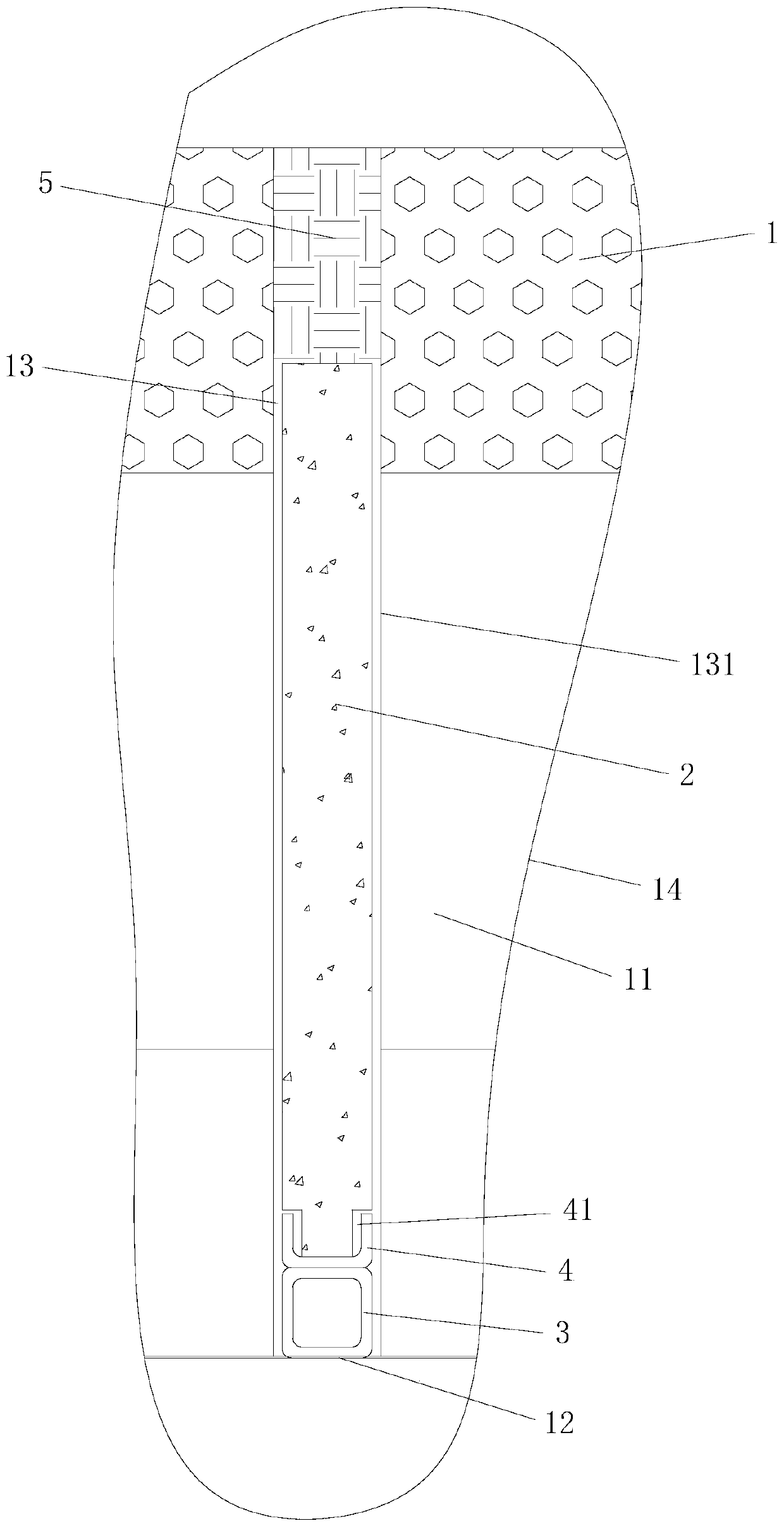
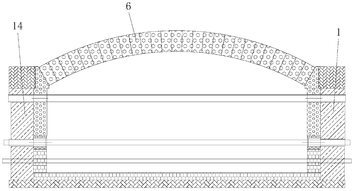
[0029] Such as figure 1 and figure 2 As shown, the roller kiln of this embodiment includes a furnace body 1 with a furnace 11, and more than one partition curtain 2 is installed in the furnace 11 through an installation assembly. The installation assembly includes a lower support beam 3 and an upper support supported on the lower support beam 3 The beam 4, the body of furnace 1 is provided with two support installation surfaces 12 which are respectively arranged on both sides of the furnace 11, the two ends of the lower support beam 3 are respectively supported and installed on the two support installation surfaces 12, and the two ends of the upper support beam 4 are respectively Correspondingly located above the two support installation surfaces 12 , the partition curtain 2 is supported and installed on the upper support beam 4 . ...


PUM


Abstract

The invention discloses a roller kiln. The roller kiln comprises a furnace body with a hearth, wherein more than one partition curtain is arranged in the hearth through a mounting assembly; the mounting assembly comprises a lower supporting cross beam and an upper supporting cross beam supported on the lower supporting cross beam; the furnace body is provided with two supporting mounting surfaceswhich are correspondingly arranged on two sides of the hearth; two ends of the lower supporting cross beam are correspondingly and correspondingly supported and arranged on the two supporting mountingsurfaces; two ends of the upper supporting cross beam are correspondingly and correspondingly positioned above the two supporting mounting surfaces; and the partition curtains are supported and arranged on the upper supporting cross beam. The roller kiln has the advantages of long service life, high safety and the like.

Description

technical field [0001] The invention relates to the technical field of heat treatment kiln equipment, in particular to a roller kiln. Background technique [0002] In the roller kiln, it is necessary to set a partition curtain in the furnace to divide the furnace into different temperature zones. The partition curtain of the existing roller kiln is to set vertical grooves on the furnace walls on both sides of the furnace, and the multiple pipes are separated from each other. Stack from bottom to top to form a partition structure. The pipe fittings are easily broken due to the corrosive gas and high temperature in the furnace. The falling of the broken pipe fittings will affect the partition effect and affect the normal production of the roller kiln, and the heat insulation of multiple stacked pipe fittings Poor performance, difficult to disassemble and maintain. [0003] In addition, the vault of the existing roller kiln is composed of multiple rows of vaults arranged in se...

Claims


Application Information

Patent Timeline
Patent Type & Authority Applications(China)
IPC IPC(8): F27B9/30F27D1/02
CPCF27B9/30F27D1/025
Inventor 欧阳建张勋郎高平立胡茂
Owner HUNAN JINLU TECH CO LTD
Why Eureka
Eureka Blog
Learn More