Method for returning self-walking device to base station and self-walking device

A self-propelled and equipment technology, applied in two-dimensional position/channel control, instruments, control/adjustment systems, etc., can solve problems such as the influence of positioning accuracy, and achieve the effect of small calculation amount, reduced complexity, and reduced occupation.

Pending Publication Date: 2020-05-01
NANJING SUMEC INTELLIGENT TECH CO LTD
View PDF5 Cites 4 Cited by
  • Summary
  • Abstract
  • Description
  • Claims
  • Application Information

AI Technical Summary

Problems solved by technology

The disadvantage of this method is that when calculating the actual position of the self-propelled device, there will be a large deviation compared with the actual position of the self-propelled device, for example, figure 2 As shown, the possible calculated position of the self-propelled device appears at figure 2 D position or B position in
This method is easily affected by the positioning accuracy. When the positioning deviates, the robot may make a circle around the field.

Method used


Image

  • Method for returning self-walking device to base station and self-walking device
  • Method for returning self-walking device to base station and self-walking device
  • Method for returning self-walking device to base station and self-walking device

Examples


Embodiment Construction

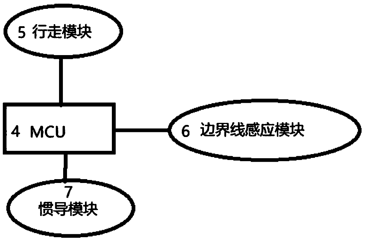
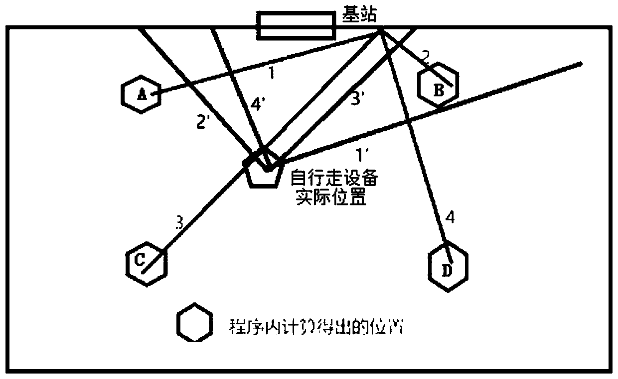
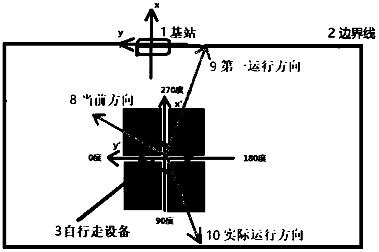
[0030] In order to make the purpose and technical solutions of the embodiments of the present invention more clear, the technical solutions of the embodiments of the present invention will be clearly and completely described below in conjunction with the drawings of the embodiments of the present invention. Apparently, the described embodiments are some, not all, embodiments of the present invention. Based on the described embodiments of the present invention, all other embodiments obtained by persons of ordinary skill in the art without creative efforts shall fall within the protection scope of the present invention.

[0031]Those skilled in the art can understand that, unless otherwise defined, all terms (including technical terms and scientific terms) used herein have the same meaning as commonly understood by those of ordinary skill in the art to which this invention belongs. It should also be understood that terms such as those defined in commonly used dictionaries should...


PUM


Abstract

The invention discloses a method for returning a self-walking device to a base station and the self-walking device. The method comprises the following steps of recording reference position parametersof the self-walking equipment in advance; when the self-walking equipment needs to return to the base station, comparing the reference position parameters with the current position and / or current direction of the self-walking equipment, and calculating to obtain a first running direction; controlling the self-walking equipment to determine an actual running direction according to the first runningdirection; and after walking to a boundary line according to the actual running direction, returning to the base station along the boundary line in a shorter path. Through recording of the referenceposition parameters, the shorter return path can be calculated when the self-walking equipment needs to return to the base station, so that the problem that the self-walking equipment needs to wind the boundary line for a circle to reach the base station due to inappropriate route direction selection in the prior art is solved.

Description

technical field [0001] The invention relates to the field of self-propelled equipment, in particular to a method for the self-propelled equipment to return to a base station and the self-propelled equipment. Background technique [0002] Intelligent self-propelled equipment has been widely popularized, and the operation of intelligent self-propelled equipment depends on electric energy. In order to ensure the stable operation of the self-propelled equipment, when the power of the self-propelled equipment is lower than a certain preset value, it will automatically return to the preset charging station. After returning to the charging station, the self-propelled device docks with the charging equipment installed in the charging station to automatically charge. [0003] At present, in the existing technology, the following three methods are generally used to control the self-propelled equipment so that it can automatically return to the preset charging station. [0004] In th...

Claims


Application Information

Patent Timeline
Patent Type & Authority Applications(China)
IPC IPC(8): G05D1/02
CPCG05D1/0225G05D1/0217
Inventor 梁凤涛周国扬郑鑫刘楷
Owner NANJING SUMEC INTELLIGENT TECH CO LTD
Why Eureka
Try Eureka