Arc extinguishing and short circuit current resisting direct-current relay

A DC relay and anti-short-circuit technology, which is applied in the direction of electromagnetic relays, electromagnetic relay details, relays, etc., can solve the problems of large difference in positive arc extinguishing effect, being subjected to Lorenz force, and reducing the short-circuit resistance of products, etc., to achieve Improve short-circuit current resistance and facilitate use

Pending Publication Date: 2020-05-01
XIAMEN HONGFA ELECTRIC POWER CONTROLS
View PDF0 Cites 4 Cited by
  • Summary
  • Abstract
  • Description
  • Claims
  • Application Information

AI Technical Summary

Problems solved by technology

[0003] The high-voltage DC relay with direct-acting magnetic circuit structure in the prior art usually adopts magnetic blowout arc extinguishing, that is, a magnetic steel is arranged around the contact point of the two moving and static contacts, and the magnetic field formed by the magnetic steel is used to realize magnetic blowout arc extinguishing. Although the magnetic arc extinguishing is beneficial to the arc extinguishing of the relay and improves the life capacity, it will also cause a problem that the energized moving reed will be subjected to the Lorentz force under the magnetic field of the magnetic blowing arc extinguishing. As a result, the Lorentz force on the moving reed under the magnetic blowout magnetic field is downward, so that the force on the moving reed is the resultant force of electric repulsion + Lorentz force. Once the resultant force is greater than the contact pressure generated by overtravel, Then the dynamic and static contacts (moving and static contacts) will not be able to reliably contact and close, resulting in the failure of the bounce and arc
[0004] The existing magnet arc extinguishing layout of the DC relay mainly includes two magnet arc extinguishing structures and four magnet arc extinguishing structures. A four magnet arc extinguishing structure in the prior art is to arrange four magnets respectively On both sides of the width of the moving reed, the positions corresponding to the moving and static contacts, and the magnetic poles on the side facing the moving and static contacts of the two magnets corresponding to the same moving and static contacts are set opposite, and corresponding to the width of the moving reed The magnetic poles of the two magnets on the same side facing the corresponding side of the moving and static contacts are set to be the same. The disadvantages of this layout of the magnets: one is that the moving reed is affected by the Loren The force is downward, which will affect the reliable contact between the dynamic and static contacts, resulting in the failure of the pop-up arc and reducing the short-circuit resistance of the product; the second is that there are polarity requirements for the load wiring, forward arc extinguishing and reverse extinguishing The effect of the arc is quite different

Method used


Image

  • Arc extinguishing and short circuit current resisting direct-current relay
  • Arc extinguishing and short circuit current resisting direct-current relay
  • Arc extinguishing and short circuit current resisting direct-current relay

Examples


Embodiment 1

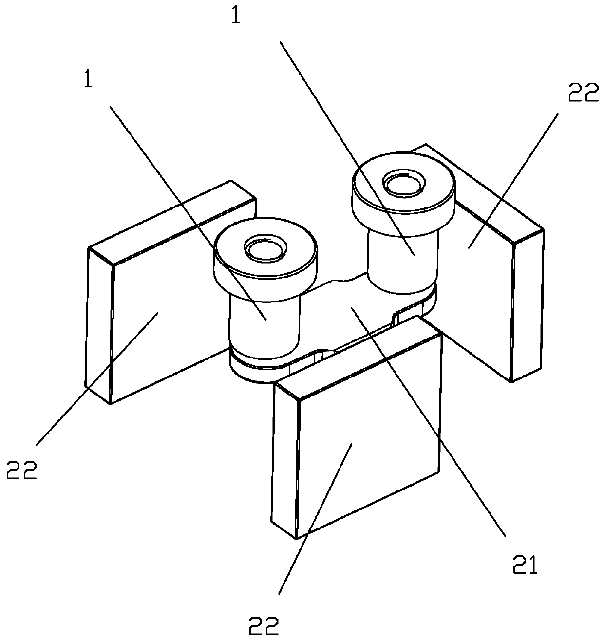
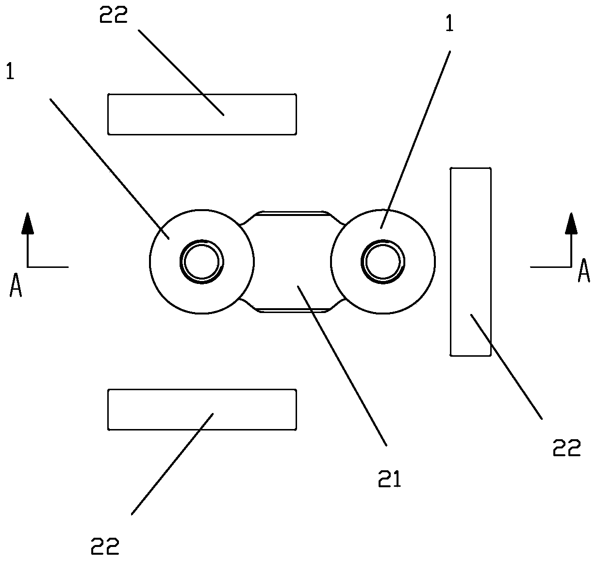
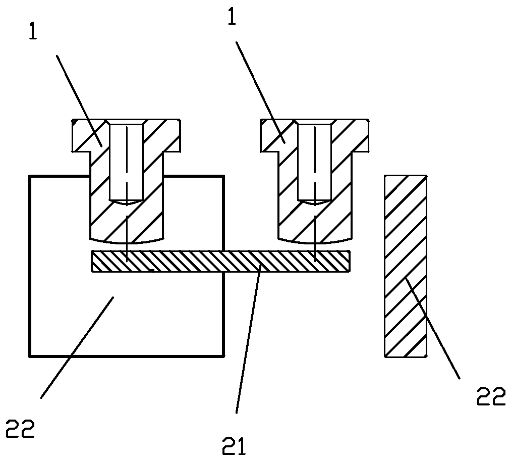
[0062] see Figure 1 to Figure 3 As shown, a kind of arc extinguishing and anti-short-circuit current DC relay of the present invention includes two static contact terminals 1, a straight piece type moving reed 21, a push rod part (not shown in the figure) and Three pieces of magnetic steel 22; the moving reed 21 is installed in the push rod part, so as to realize the moving contact at the two ends of the moving reed 21 and the static contact at the bottom of the two static contact lead-out ends 1 under the action of the pushing rod part Matching; in this embodiment, the two ends of the moving reed 21 constitute the moving contact of the moving reed 21, and the bottom end of the static contact lead-out 1 constitutes the static contact of the static contact lead-out 1; Among the three magnets 22, two magnets 22 are arranged on the outsides of the two sides of the width of the moving reed 21 respectively, and are in a position corresponding to one of the moving and static contac...

Embodiment 2

[0068] see Figure 4 to Figure 8 As shown, the DC relay of a kind of arc extinguishing and anti-short circuit current of the present invention is different from Embodiment 1 in that it also includes two U-shaped yoke clips 23, and the U of one yoke clip 23 (left side) The two sides of the type are respectively connected to the side of the two magnetic steels 22 (left side) facing away from the moving and static contacts, and the U-shaped bottom edge of one of the yoke clips 23 (left side) is in the The outside of the other side (left side) of the length of moving reed 21; The two sides of the U shape of the other yoke clip 23 (on the right) are respectively located outside the two sides of the width of the moving reed 21 and correspond to the other moving and static contacts (on the right).

[0069] In this embodiment, the sides of the three magnets 22 facing the dynamic and static contacts are all set as S poles. The blowing direction of the formed arc extinguishing magneti...

Embodiment 3

[0072] see Figure 9 to Figure 16 As shown in the present invention, a DC relay for arc extinguishing and anti-short circuit current, the push rod part includes a first U-shaped bracket 31 in an inverted shape, a spring 32, a spring seat 33 and a push rod 34, and the push rod 34 is fixed to the spring seat 33, the bottom of the first U-shaped bracket 31 is fixed to the spring seat 33, and the moving reed 21 is installed on the first U-shaped bracket 32 ​​through the spring 32. In the bracket 31; the difference from the second embodiment is that the moving reed 21 is also equipped with an anti-short circuit structure with at least two magnetic conducting rings formed by the combination of the upper yoke and the lower armature. When the reed has a fault and a large current, it can generate suction in the direction of the contact pressure to resist the electrodynamic repulsion between the movable reed and the terminal of the static contact due to the fault current.

[0073] In t...


PUM


Abstract

The invention discloses an arc extinguishing and short circuit current resisting direct-current relay, which comprises two static contact leading-out ends, a straight sheet type movable contact spring, a push rod component and three pieces of magnetic steel. Two of the three pieces of magnetic steel are respectively arranged at the outer sides of two sides of the width of the movable contact spring and are positioned at the position corresponding to one movable and static contact, and the magnetic poles of one surfaces of the two pieces of magnetic steel, which face the movable and static contact, are set to be the same; the other piece in the three pieces of magnetic steel is arranged on the outer side of one side of the length of the movable contact spring and is positioned at the position corresponding to the other movable and static contact; and the pole surface of the other piece of magnetic steel is approximately vertical to the pole surfaces of the two pieces of magnetic steel,so that the Lorentz force generated by the movable contact spring in an arc extinguishing magnetic field formed by the three pieces of magnetic steel is approximately zero. The defect that the short circuit current resisting capability of the product is reduced due to an arc extinguishing magnetic field can be eliminated.

Description

technical field [0001] The invention relates to the technical field of relays, in particular to a DC relay capable of extinguishing arcs and resisting short-circuit current. Background technique [0002] The anti-short-circuit capability of DC relays is a relatively difficult indicator at present. At present, the anti-short-circuit current of high-voltage DC relays has reached the level of 16kA. When the short-circuit current passes through the movable and static contacts, the electric repulsion generated between the movable and static contacts will cause the contacts to repel, which will eventually lead to severe arcing and make the relay invalid. The root of solving short-circuit resistance is to ensure that the contacts are in reliable contact without bouncing off. [0003] The high-voltage DC relay with direct-acting magnetic circuit structure in the prior art usually adopts magnetic blowout arc extinguishing, that is, a magnetic steel is arranged around the contact poi...

Claims


Application Information

Patent Timeline
Patent Type & Authority Applications(China)
IPC IPC(8): H01H50/36H01H50/38H01H50/18H01H50/56H01H9/44
CPCH01H9/44H01H9/443H01H50/18H01H50/36H01H50/38H01H50/56
Inventor 代文广王萌
Owner XIAMEN HONGFA ELECTRIC POWER CONTROLS
Why Eureka
Try Eureka