Main transformer radiator cooling device with photovoltaic conversion function and use method thereof

A main transformer, photovoltaic conversion technology, applied in the direction of transformer/inductor cooling, temperature control by electric method, refrigerator, etc., can solve the problems of overload and short-circuit current resistance, main transformer burning and explosion, low cooling efficiency and other problems , to achieve the effect of improving overload and short-circuit current resistance, extending operating life and overall economical operation

Inactive Publication Date: 2014-12-03
STATE GRID CORP OF CHINA +6
View PDF8 Cites 1 Cited by
  • Summary
  • Abstract
  • Description
  • Claims
  • Application Information

AI Technical Summary

Problems solved by technology

[0002] During the operation of the main transformer, its winding and iron core will generate heat under the action of electricity and magnetism. If the heat is not taken away in time at this time, it will lead to serious accidents such as failure of the main transformer or even burning and explosion. The cooling of the main transformer The method is to cool the winding by the transformer oil circulating inside the main transformer. After cooling the winding, the heated transformer oil needs to be cooled by heat exchange through the radiator and then enter the main transformer to circulate and cool the winding. Traditional main transformer radiators The cooling methods are fan blowing, natural heat dissipation, etc. These two cooling methods use air at ambient temperature as the refrigerant, the cooling efficiency is very low, the cooling range is small, and they are greatly affected by environmental factors, which often cause copper and iron losses in the main transformer. Large, overload and short-circuit resistance, short insulation life and insufficient safety level, etc.

Method used


Image

  • Main transformer radiator cooling device with photovoltaic conversion function and use method thereof
  • Main transformer radiator cooling device with photovoltaic conversion function and use method thereof
  • Main transformer radiator cooling device with photovoltaic conversion function and use method thereof

Examples


Embodiment Construction

[0026] The present invention will be further described below in conjunction with the accompanying drawings and specific embodiments.

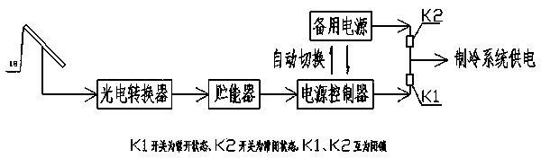
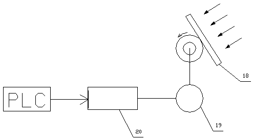
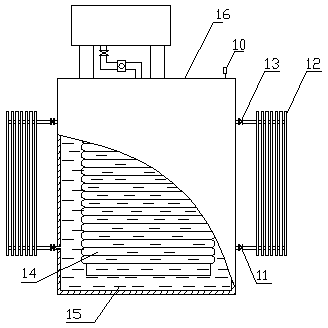
[0027] Such as Figure 1-10 As shown, the main transformer radiator cooling device with photovoltaic conversion function includes photovoltaic conversion system, cooling cover 2, refrigeration compressor 4, condenser 6, throttle valve 9, oil flow cooling circulation system, temperature sensor 10, control module , the refrigeration compressor 4 is electrically connected to the photovoltaic conversion system, and the photovoltaic conversion system converts solar energy into qualified electric energy required for the refrigeration compressor 4 to work, and the oil flow cooling circulation system is arranged in the main transformer 16 used to cool the winding 14, the transformer oil 15 flowing in the main transformer 16 is heated after cooling the winding 14 in the main transformer 16, and the heated heat transformer oil 15 in the oil flow cooling ...


PUM


Abstract

The invention relates to a main transformer radiator cooling device with a photovoltaic conversion function and a use method thereof. A refrigeration compressor is electrically connected with a photovoltaic conversion system, the photovoltaic conversion system converts solar energy into qualified electric energy needed for the refrigeration compressor to work, an oil flow cooling circulation system is arranged in a main transformer and used for cooling windings, transformer oil in the oil flow cooling circulation system flows into a radiator to be cooled through an oil outlet valve on the upper portion of the main transformer, flows out from the radiator through an oil inlet valve on the lower portion of the main transformer and then flows into the main transformer, the radiator is shielded in a cavity of a cooling cover and tightly sealed through the cooling cover, and refrigerant media flow in the cooling cover circularly and are used for cooling the transformer oil flowing in the radiator.

Description

technical field [0001] The invention relates to a main transformer radiator cooling device with photovoltaic conversion function and a use method. Background technique [0002] During the operation of the main transformer, its winding and iron core will generate heat under the action of electricity and magnetism. If the heat is not taken away in time at this time, it will lead to serious accidents such as failure of the main transformer or even burning and explosion. The cooling of the main transformer The method is to cool the winding by the transformer oil circulating inside the main transformer. After cooling the winding, the heated transformer oil needs to be cooled by heat exchange through the radiator and then enter the main transformer to circulate and cool the winding. Traditional main transformer radiators The cooling methods are fan blowing, natural heat dissipation, etc. These two cooling methods use air at ambient temperature as the refrigerant, the cooling effic...

Claims


Application Information

Patent Timeline
Patent Type & Authority Applications(China)
IPC IPC(8): H01F27/08H01F27/40F25B41/06G05D23/19F25B41/30
CPCY02B30/70
Inventor 林晓铭陈铭郑东升涂恩来林舒妍郑孝章
Owner STATE GRID CORP OF CHINA
Why Eureka
Try Eureka