Cooling device for dry-type transformer and using method

A technology for dry-type transformers and cooling devices, which is applied in the direction of transformer/inductor cooling and temperature control using electric methods. It can solve problems such as overload and short-circuit resistance, dry-type transformer burnout, and short insulation life. Improve overload and short-circuit current resistance, ensure safe operation, and prolong service life

Inactive Publication Date: 2014-11-19
STATE GRID CORP OF CHINA +6
View PDF6 Cites 4 Cited by
  • Summary
  • Abstract
  • Description
  • Claims
  • Application Information

AI Technical Summary

Problems solved by technology

[0002] During the operation of the dry-type transformer, under the action of electricity and magnetism, its winding and iron core will generate heat. Due to the unique design and operation mode of the dry-type transformer, its own heat dissipation effect is very poor. If the heat cannot be taken away in time at this time , will lead to serious accidents of dry-type transformer burning or even explosion. Traditional dry-type transformers are cooled by fans or natural cooling. The cooling efficiency of these two cooling methods is very low, the cooling range is small, and they are greatly affected by environmental factors. , often lead to many shortcomings such as large copper and iron losses of dry-type transformers, small overload and short-circuit resistance capabilities, short insulation life, and insufficient safety levels.

Method used


Image

  • Cooling device for dry-type transformer and using method
  • Cooling device for dry-type transformer and using method
  • Cooling device for dry-type transformer and using method

Examples


Embodiment Construction

[0022] The present invention will be described in further detail below in conjunction with the accompanying drawings and specific embodiments.

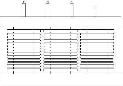
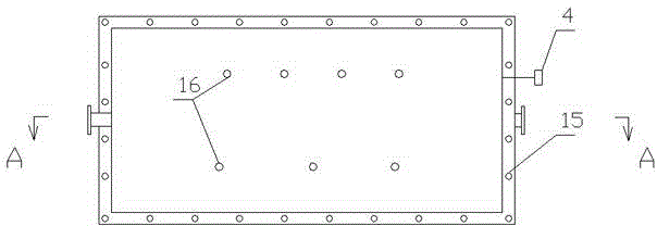
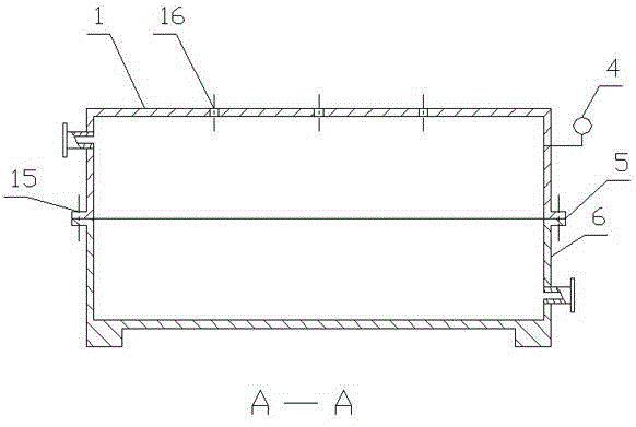
[0023] like Figure 1~8 As shown, a dry-type transformer cooling device includes a cooling chamber, a refrigeration system and a control module. The round hole through which the low-voltage bushing passes, and the part of the bushing passing through the round hole is tightly sealed by the sealing ring. The dry-type transformer is fixed in the cavity of the cooling chamber, and the cooling medium circulates in the cooling chamber. The heat generated by the dry-type transformer is taken away. The refrigeration system performs a refrigeration cycle on the refrigerant medium to meet the requirements of the refrigerant medium for cooling the dry-type transformer. An inlet valve for the refrigerant is installed on the lower side of the cooling chamber. The other pair of cooling chambers The outlet valve for the refrigerant is installed on ...


PUM


Abstract

The invention relates to a cooling device for a dry-type transformer. The cooling device comprises a cooling chamber, a refrigerating system and a control module. The cooling chamber is divided into an upper shell and a lower shell, round holes for a high-voltage sleeve and a low-voltage sleeve to penetrate through are formed in the top of the upper shell, and the portions, penetrating out of the round holes, of the sleeves are sealed tightly by sealing rings; the dry-type transformer is fixed in a cavity of the cooling chamber, a refrigerant medium circularly flows in the cooling chamber, and refrigeration cycle is performed on the refrigerant medium by the refrigerating system, so that the requirement for cooling the dry-type transformer through the refrigerant medium is met; an inlet valve for the refrigerant medium to enter is installed on the lower portion of the side face of the cooling chamber, an outlet valve for the refrigerant medium to exit is installed on the upper portion of the other opposite side face of the cooling chamber, and a temperature sensor is installed on the upper portion of the side face of the cooling chamber; the control module is electrically connected with the temperature sensor and a refrigeration compressor in the refrigerating system and automatically controls the refrigeration compressor to work according to on-line temperature valves measured and transmitted by the temperature sensor.

Description

technical field [0001] The invention relates to a dry-type transformer cooling device and a using method. Background technique [0002] During the operation of the dry-type transformer, under the action of electricity and magnetism, its winding and iron core will generate heat. Due to the unique design and operation mode of the dry-type transformer, its own heat dissipation effect is very poor. If the heat cannot be taken away in time at this time , will lead to serious accidents of dry-type transformer burning or even explosion. Traditional dry-type transformers are cooled by fans or natural cooling. The cooling efficiency of these two cooling methods is very low, the cooling range is small, and they are greatly affected by environmental factors. , often lead to dry-type transformers with many shortcomings such as large copper and iron losses, small overload and short-circuit resistance capabilities, short insulation life, and insufficient safety levels. Contents of the i...

Claims


Application Information

Patent Timeline
Patent Type & Authority Applications(China)
IPC IPC(8): H01F27/08G05D23/19
Inventor 林晓铭连鸿松林舒妍郑孝章连文杰
Owner STATE GRID CORP OF CHINA
Why Eureka
Try Eureka