
PCIE exchange chip port configuration system and method

A technology for switching chips and configuring systems, which is applied in transmission systems, digital transmission systems, data switching networks, etc., and can solve problems such as difficult to find PCIE switching chips

Active Publication Date: 2020-05-01
成都华大九天科技有限公司
View PDF5 Cites 2 Cited by
  • Summary
  • Abstract
  • Description
  • Claims
  • Application Information

AI Technical Summary

Problems solved by technology

Although there are many PCIE switch chips on the market, it is difficult to find literature on the specific implementation mechanism of the PCIE switch chip port configuration. This patent proposes a PCIE switch chip port configuration implementation mechanism, which can quickly realize the port configuration of the PCIE switch chip. , to meet the PCIE protocol's time limit requirements for PCIE chip initialization

Method used


Image

  • PCIE exchange chip port configuration system and method
  • PCIE exchange chip port configuration system and method

Examples


Embodiment 1

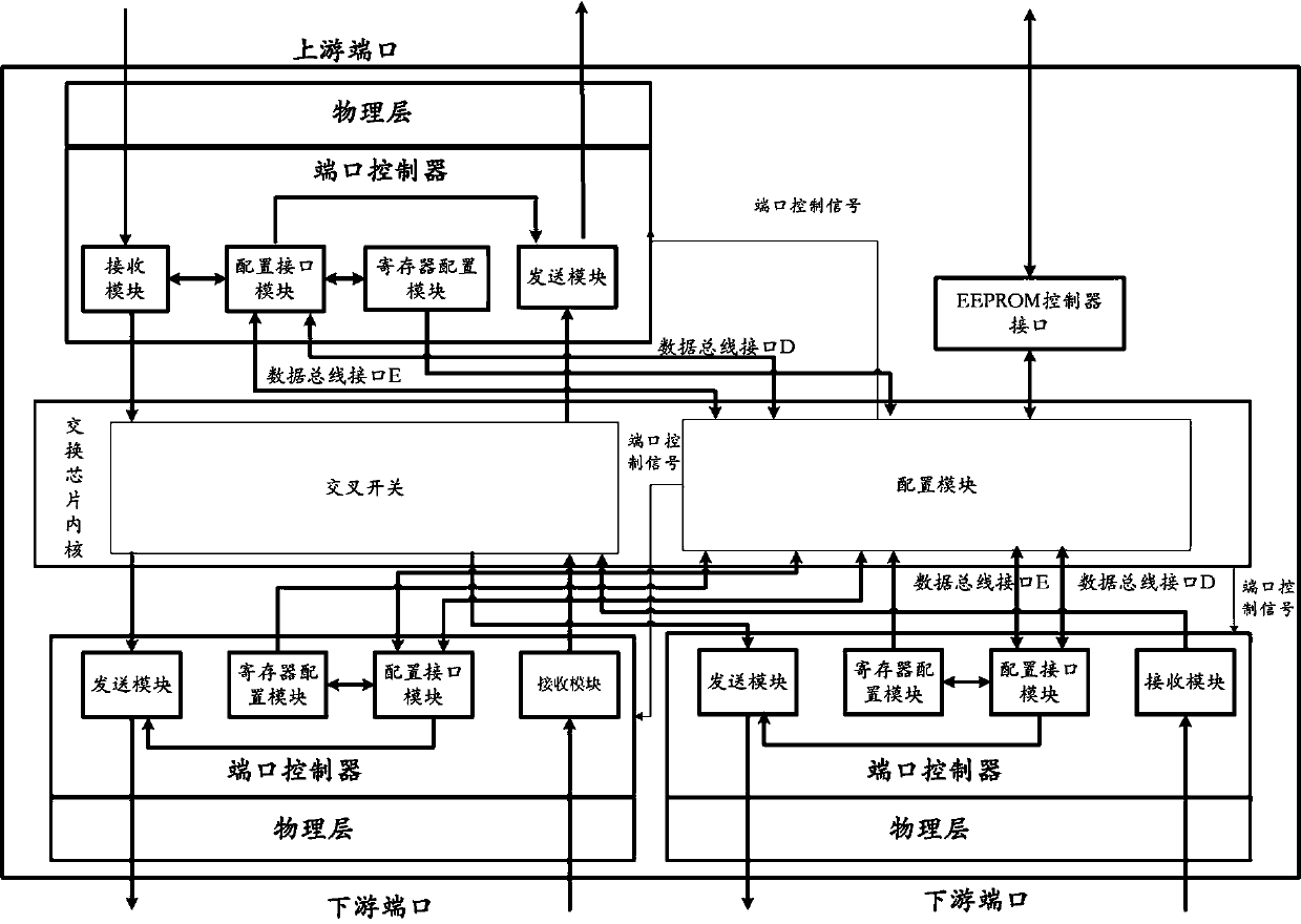
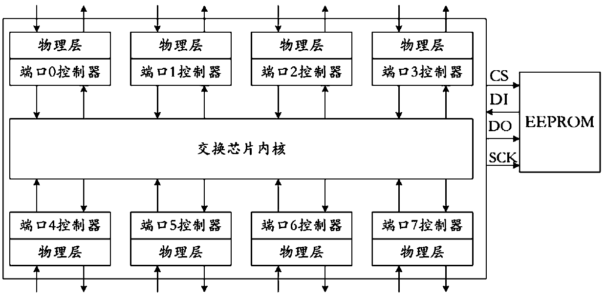
[0078] figure 1 For the PCIE switch chip port configuration system structural representation according to the present invention, as figure 1 As shown, the PCIE switch chip port configuration system of the present invention mainly includes a switch chip core, a port controller, and an EEPROM controller interface module. In this system, a piece of EEPROM is externally connected to the PCIE switch chip, and it is initialized and loaded through the external EEPROM. In general, the PCIE switch chip port configuration system has n ports, where n is a natural number not less than three, and each port receives data from the external PCIE link through its entry-side physical layer and port controller input side, and the received data It is directly processed by the port controller, and the receiving port controller can also forward the received data packet to the switch chip core according to the situation, and then forwarded by the switch chip core to the port controller of other por...

Embodiment 2

[0098] The detailed processing flow of the port configuration implementation mechanism of the PCIE switch chip port configuration system is as follows:

[0099] Power on the PCIE switch chip, read the configuration information from the external EEPROM, and send it to the configuration module.

[0100] In this step, during the power-on process of the PCIE switch chip, if it is judged that there is an external EEPROM chip, and the first byte read from the EEPROM is 5Ah, it means that the EEPROM is not empty, and the EEPROM controller interface module is connected from the external Read the configuration information of each port configuration register in the EEPROM and send it to the configuration module.

[0101] The configuration module receives the configuration information from the interface of the external EEPROM controller, according to the configured port number, sends it to the configuration interface module in the port controller of the corresponding port through the dat...


PUM


Abstract

The invention discloses a PCIE (Peripheral Component Interconnect Express) exchange chip port configuration system and method. The comprises an exchange chip kernel, a plurality of ports and an EEPROM (Electrically Erasable Programmable Read-Only Memory) controller interface; the exchange chip kernel further comprises a crossbar switch and a configuration module; the crossbar switch is used for forwarding a transaction layer packet passing through the PCIE exchange chip; the configuration module is used for configuring the port, configuring the port as an upstream port or a downstream port, and controlling the opportunity of establishing a link for each port link; the upstream port receives configuration from an upstream link and configuration of the configuration module, and performs read or write operation on a port configuration register unit in the upstream port; and the downstream port receives the configuration information from the configuration module and performs reading or writing operation on the port configuration register unit in the downstream port. According to the system and method, the port configuration can be quickly completed, and the time limit requirement of aPCIE protocol on PCIE chip initialization is met.

Description

technical field [0001] The present invention relates to the technical field of high-speed interconnection bus (Peripheral Component Interconnect Express, PCIE) of computer peripheral equipment, in particular to a PCIE switch chip port configuration system and method. Background technique [0002] The PCIE bus is based on the traditional PCI system, retains some excellent features of the traditional PCI bus, and is compatible with the PCI bus in terms of software configuration. The PCIE bus changes the parallel bus structure of PCI to serial to break through the speed bottleneck, and at the same time uses point-to-point connections, CRC checks, etc. to ensure high real-time and high reliability of the data bus. A high-performance, general-purpose I / O interconnect bus defined for a variety of computing and communication platforms. The PCIE bus is currently widely used in computing systems such as workstations and servers, as well as embedded computing and communication platfo...

Claims


Application Information

Patent Timeline
IPC IPC(8): H04L12/931H04L12/933H04L12/935H04L49/111
CPCH04L49/10H04L49/109H04L49/30H04L49/102
Inventor 杨珂张建杰赵姣张建波崔飞飞
Owner 成都华大九天科技有限公司
Learn More