Duct type cooling fan

A ducted and fan technology, which is applied in the direction of refrigerators, refrigeration components, refrigeration and liquefaction, etc., can solve the problems of poor cooling effect of refrigeration fans, and achieve the effect of accelerating cooling and increasing the contact area

Pending Publication Date: 2020-05-05
宁波凡浦智能科技有限公司
View PDF1 Cites 0 Cited by
  • Summary
  • Abstract
  • Description
  • Claims
  • Application Information

AI Technical Summary

Problems solved by technology

[0006] Aiming at the deficiencies of the prior art, the present invention provides a ducted cooling fan, which mainly solves the problem that the cooling effect of the ducted cooling fan that needs to be turned on at a high wind speed is poor

Method used


Image

  • Duct type cooling fan
  • Duct type cooling fan
  • Duct type cooling fan

Examples


Embodiment 1

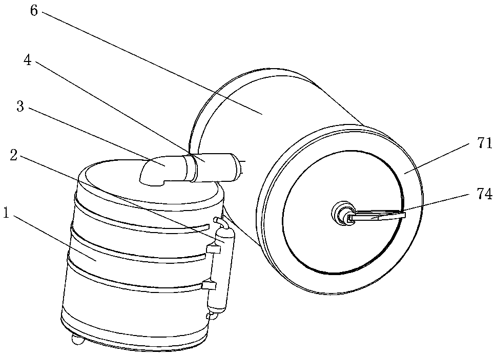
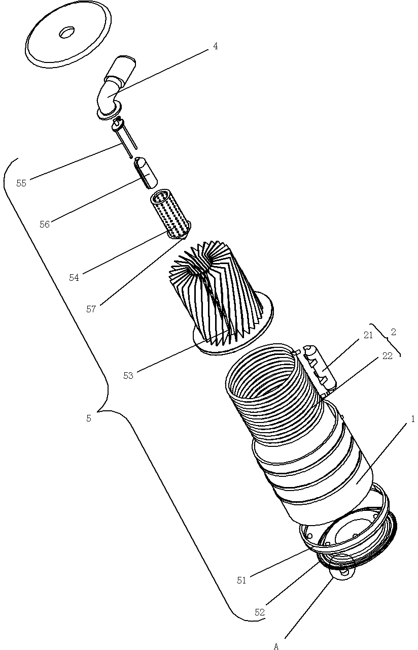
[0034] Such as figure 1 , 3, 4, 5, and 7, the embodiment of the present invention provides a ducted refrigeration fan, including a cooling cylinder 1, the upper end of the cooling cylinder 1 is connected with an air guide pipe 3, and the other end of the air guide pipe 3 is connected with a suction fan 4, The surface of the suction fan 4 is fixedly connected with the cooling cylinder 1, and the other end of the suction fan 4 is connected with a pipeline 6, which is vertically arranged with the cooling cylinder 1, and the surface of the pipeline 6 is fixedly connected with the cooling cylinder 1, and the surface of the cooling cylinder 1 is provided with The cooling mechanism 2, the cooling mechanism 2 includes a compressor 21, the surface of the compressor 21 is fixedly connected to the surface of the cooling cylinder 1, the port of the cooling cylinder 1 is connected with an exchange tube 22, and the surface of the exchange tube 22 runs through the side wall of the cooling cy...

Embodiment 2

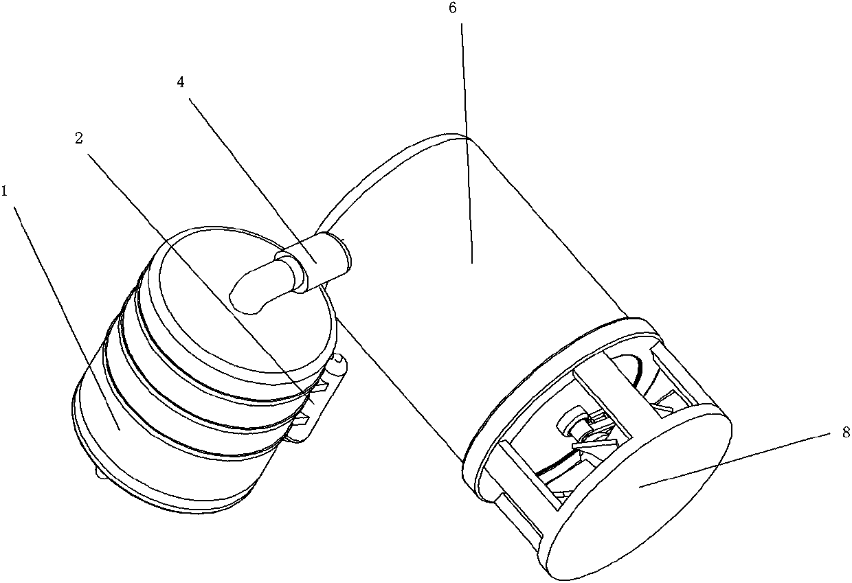
[0038] Such as figure 2 , 6 As shown, the embodiment of the present invention provides a ducted refrigeration fan. On the surface of the upper limit ring 71 of the specific embodiment 1, an air guiding device 8 is fixedly connected. The air guiding device 8 includes a connecting piece 801, one end of the connecting piece 801 and The limit ring 71 is fixedly connected, the other end of the connecting piece 801 is fixedly connected with a baffle 802, the size of the baffle 802 is suitable for the limit ring 71, and the end of the baffle 802 close to the limit ring 71 is rotatably connected with a wind deflector 803 , using the air guiding device 8 to prevent the cold air from being directly blown out by the pipe 6 .


PUM


Abstract

The invention provides a duct type cooling fan and relates to the technical field of duct type cooling fans. The duct type cooling fan comprises a cooling cylinder; the upper end of the cooling cylinder communicates with an air guide pipe; the other end of the air guide pipe communicates with a suction fan; the surface of the suction fan is fixedly connected with the cooling cylinder; and the other end of the suction fan communicates with a pipeline. By starting the fan, the suction fan can be used for sucking air from the inside of the cooling cylinder by using the air guide pipe; a filter cylinder which is positioned inside the cooling cylinder and communicates with the air guide pipe is used for sucking air at the center of exchange blades; a conical air guide hopper positioned at the bottom end of the filter core is used for discharging the air which flows in via the bottom of a rotating disc into gaps among the exchange blades; the exchange blades made of metal are used for sucking cold air which is generated at the surface of an exchange pipe; a compressor and the exchange pipe cooperate with each other to realize cooling ; the contact area between the cold air and the air isincreased by utilizing the exchange blades, and thus air cooling is quickened; and the cooled air is sucked into the pipeline by virtue of the suction fan, thereby solving the problem about relatively poor cooling effect of the duct type cooling fan which needs to start high air speed when high temperature is generated due to high-speed running of a motor.

Description

technical field [0001] The invention relates to the technical field of ducted cooling fans, in particular to a ducted cooling fan. Background technique [0002] The ducted fan can generate greater wind force than the isolated fan of the same diameter, and the fan ring is enclosed in the duct, which can not only prevent the aerodynamic sound of the fan from spreading outward, but also has a compact structure and high safety. For refrigeration, a compression condensing pipe is often laid inside the duct. When the speed of the fan in the duct is increased, the airflow will pass through the duct quickly, and the contact time between the fast-flowing airflow and the condensation pipe will be shortened, and the high-speed flowing gas will Self-generating friction in motion generates heat, and the high speeds of the motor generate high temperatures, resulting in ineffective cooling when high-velocity airflow is required. [0003] Compared with the double-duct fan whose application...

Claims


Application Information

Patent Timeline
Patent Type & Authority Applications(China)
IPC IPC(8): F25B1/00F25B43/00
CPCF25B1/00F25B43/003
Inventor 沈泽
Owner 宁波凡浦智能科技有限公司
Why Eureka
Try Eureka