Wireless control system and wireless control method for realizing power supply on-off operation of equipment

A wireless control, on-off operation technology, applied in signal transmission systems, instruments, etc., can solve the problems of low energy absorption and utilization by wireless switching devices, increased costs, and energy waste.

Active Publication Date: 2020-05-05
GUANGDONG UNIV OF TECH
View PDF5 Cites 2 Cited by
  • Summary
  • Abstract
  • Description
  • Claims
  • Application Information

AI Technical Summary

Problems solved by technology

[0004] In order to solve the problem of standby power consumption, although various zero-power standby schemes have appeared, there are still many problems in these schemes, which need to be further improved and perfected.
For example, because the control signal of the existing wireless switch remote control device needs to cover a certain range to achieve operational convenience, precise directional transmission cannot be used, and the wireless energy transmission, reception and conversion process itself has relatively large losses, making wireless energy transmission efficient. Not too high, the final energy absorbed and utilized by the wireless switch device is very low, and most of the energy is radiated into the air and wasted
Another example is that the existing wireless switch remote control device needs to consume a large amount of wireless energy. Even if a high-priced, large-capacity battery is used for power supply at the remote control end, its working life will be greatly limited, and the cost will be increased.
For another example, if considering the need to ensure that the remote control signal of the wireless switch device can cover a certain range, especially hoping to achieve accurate directional transmission, then a higher requirement is proposed for the wireless switch remote control device (especially the two parts of the power amplifier and the transmitting antenna) requirements, and the existing ordinary power amplifiers and on-board patch antennas are difficult to meet the requirements, so if this kind of wireless switch device is to be used, it is necessary to increase the volume of the remote control terminal, which will bring many problems to daily applications and manufacturing costs. Negative Effects

Method used


Image

  • Wireless control system and wireless control method for realizing power supply on-off operation of equipment
  • Wireless control system and wireless control method for realizing power supply on-off operation of equipment
  • Wireless control system and wireless control method for realizing power supply on-off operation of equipment

Examples


Embodiment approach

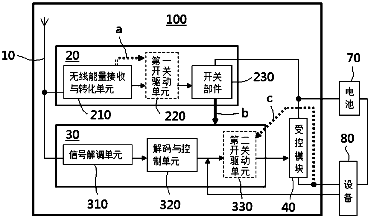
[0059] Such as image 3 As shown, one end of the wireless energy receiving and converting unit 210 is connected to the transceiver antenna 10, and the other end is connected to the switch component 230 or the first switch driving unit 220 (if selected). The wireless energy receiving and converting unit 210 is used to receive wireless energy and convert it into a DC signal. The above-mentioned first switch driving unit 220 can be powered by the above-mentioned DC signal converted and generated by the wireless energy receiving and converting unit 210 before and after the switch part 230 enters the closed state, which is image 3 The connecting lines between them have been schematically marked with the reference symbol a. In some implementations, the wireless energy receiving and converting unit 210 can optionally be configured such that the provided DC signal can ensure that the control module 30 remains electrically connected to the power supply before outputting the control s...


PUM


Abstract

The invention discloses a wireless control system and a wireless control method for realizing power supply on-off operation of equipment. The wireless control system comprises a wireless switching device and a wireless remote control device; the wireless switching device is used for being arranged between a power supply and equipment which is in a passive standby state when power is not supplied and comprises a transceiving antenna, a passive awakening module, a control module and a controlled module, the passive wake-up module is connected with the transceiving antenna and converts the received wireless energy signal into a direct current signal so that the control module is powered and outputs a control signal and the controlled module is enabled to perform on-off operation between the equipment and the power supply. The wireless remote control device is matched with the wireless switching device and comprises a transceiving antenna and a remote control module. With application the technical scheme of the invention, the standby power consumption of various types of equipment can be thoroughly eliminated, the on-off operation between the equipment and the power supply can be conveniently and quickly realized, and remarkable social benefits and economic benefits can be realized.

Description

technical field [0001] The invention relates to the technical field of switch control, and in particular to a wireless control system and a wireless control method for realizing on-off operation of power supply of equipment. Background technique [0002] With the increasing global warming, energy saving and emission reduction has become the top priority of the governments of various countries, especially the electrical and electronic industries, which are closely related to daily life and production, have been pushed to the forefront. For example, in the European and American markets, high Efficiency and low power consumption have become one of the important factors that must be considered in the research and development process of electronic products, which are more competitive in the market. [0003] The standby power consumption of various electronic devices has become one of the important problems to be solved for energy saving and emission reduction. However, there are ...

Claims


Application Information

Patent Timeline
IPC IPC(8): G08C17/02
CPCG08C17/02
Inventor 马建国周绍华
Owner GUANGDONG UNIV OF TECH
Why Eureka
Try Eureka