A low-profile two-dimensional Fresnel zone plate antenna based on planar aperture space feeding

A low-profile, planar technology, applied in the direction of basically flat resonant elements, antennas, slot antennas, etc., can solve the problems of high antenna profile, unsatisfactory phase difference, and restricted spherical wave incidence due to Fresnel diffraction patterns, and achieve The principle is simple and easy to understand, and the effect of a wide range of applications

Active Publication Date: 2021-03-05
ZHEJIANG UNIV
View PDF4 Cites 0 Cited by
  • Summary
  • Abstract
  • Description
  • Claims
  • Application Information

AI Technical Summary

Problems solved by technology

If it is placed too far away, the phase difference on the Fresnel zone plate cannot satisfy the Fresnel diffraction pattern that forms a specific beam pointing, and increases the antenna profile
[0003] Considering comprehensively, the traditional Fresnel zone plate antenna has the following main problems: 1. The formation of Fresnel diffraction patterns is limited by the incidence of spherical waves
2. It is difficult to determine the optimal placement distance of the feed; 3. Loss caused by oblique incidence
4. High antenna profile;

Method used


Image

  • A low-profile two-dimensional Fresnel zone plate antenna based on planar aperture space feeding
  • A low-profile two-dimensional Fresnel zone plate antenna based on planar aperture space feeding
  • A low-profile two-dimensional Fresnel zone plate antenna based on planar aperture space feeding

Examples


Embodiment Construction

[0046] The present invention will be further described and illustrated below in conjunction with drawings and examples: this example is based on the technical solution of the present invention, and the scope of protection of the present invention includes but is not limited to the following examples.

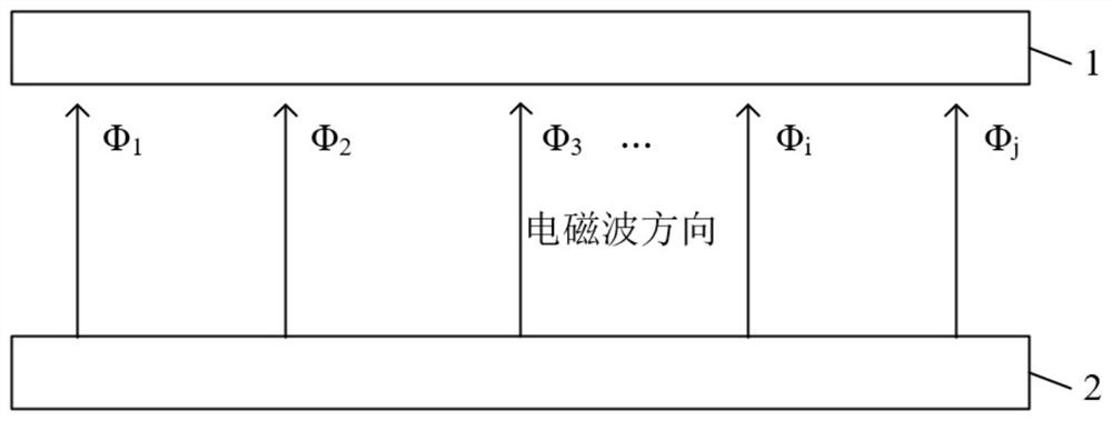
[0047] like figure 1 As shown, the two-dimensional Fresnel zone plate antenna consists of a two-dimensional Fresnel zone plate 1 and a low-profile planar aperture feed 2 . The plane aperture feed is placed close to the Fresnel zone plate and kept parallel to the Fresnel zone plate. The phase of the outgoing electromagnetic wave of the plane aperture feed is randomly distributed on the surface of the Fresnel zone plate. figure 1 Middle Ф 1 , Ф 2 , Ф 3 , Ф i , Ф j represent different phase values ​​respectively.

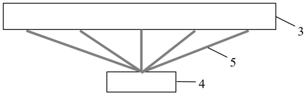
[0048] figure 2 It is a structural block diagram of a low-profile plane aperture feed source, which consists of a plane aperture antenna 3 and a power dividing...


PUM


Abstract

The invention discloses a low-profile two-dimensional Fresnel zone plate antenna based on plane aperture space feeding. The planar aperture feed feeds the two-dimensional Fresnel zone plate in close space; the planar aperture feed and the Fresnel zone plate have the same size and the insulation connection is fixed; the planar aperture feed includes a composite or separate independent planar aperture antenna and power The planar aperture antenna adopts the antenna structure of the planar patch antenna array or the planar slot / opening array; the power dividing network feeds the planar aperture antenna to generate outgoing electromagnetic waves, and the outgoing electromagnetic waves are vertically incident on the two-dimensional Fresnel zone plate. By adjusting the phase shift function, the network makes the phase of the outgoing electromagnetic wave present a gradient distribution from the center to the outside on the surface of the two-dimensional Fresnel zone plate. The invention adopts different plane aperture feed sources to form generalized Fresnel diffraction patterns on the Fresnel zone plate, and utilizes the phase shifting capability of the Fresnel zone plate with reconfigurable phase to realize the two-dimensional Fresnel zone plate antenna. dimensional beam scanning.

Description

technical field [0001] The invention belongs to the field of two-dimensional beam scanning Fresnel zone plate antennas, in particular to a low-profile two-dimensional Fresnel zone plate antenna based on plane aperture space feeding. Background technique [0002] The traditional Fresnel zone plate antenna consists of a Fresnel zone plate and a spherical wave space feed represented by a horn antenna. According to Huygens' principle, the radiation far field is obtained by the coherent superposition of the radiation field at each point of the Fresnel zone plate as the secondary emission source. The different paths of the spherical wave incident on each point of the Fresnel zone plate lead to the different phases of the secondary emission sources. Among all the paths where the outgoing wave of the secondary transmitting source reaches the far-field beam, the shortest path is used as the reference path, and the phase at its position is used as the reference phase. The difference...

Claims


Application Information

Patent Timeline
Patent Type & Authority Patents(China)
IPC IPC(8): H01Q1/38H01Q1/50H01Q3/46H01Q9/04H01Q13/10H01Q19/18H01Q21/00
CPCH01Q1/38H01Q1/50H01Q3/46H01Q9/0407H01Q13/10H01Q19/18H01Q21/00
Inventor 席强丽冉立新
Owner ZHEJIANG UNIV
Why Eureka
Try Eureka