
Variable transmission ratio rack gear shaping force prediction method

A technology of variable transmission ratio and prediction method, applied to components with teeth, gear teeth manufacturing devices, gear teeth, etc., can solve the problems of uneven cutting, difficult prediction of gear shaping force, and easy generation of cutting vibration.

Active Publication Date: 2020-05-08
WUHAN UNIV OF TECH
View PDF4 Cites 2 Cited by
  • Summary
  • Abstract
  • Description
  • Claims
  • Application Information

AI Technical Summary

Problems solved by technology

Due to the need to achieve a variable transmission ratio, the variable transmission ratio rack has a complex and variable non-standard tooth shape along the length direction, resulting in uneven cutting during the gear shaping process of the variable transmission ratio rack, which is prone to cutting vibration, which is harmful to the processing The precision of the formed tooth surface has a great influence, and the existing research on the prediction of the gear shaping force mainly focuses on the standard cylindrical gear, the cutting process is relatively uniform and stable, and the gear shaping process of the variable transmission ratio rack with uneven cutting The prediction of gear shaping force is relatively small, and the cutting area and contact length are different in each step of cutting, which makes it difficult to predict the gear shaping force in the gear shaping process of variable transmission ratio racks. Therefore, based on the variable transmission ratio gear It is of great significance to propose a new accurate and efficient algorithm to calculate the cutting area and cutting contact length, and then realize the prediction of gear shaping force.
There is no report on the prediction of gear shaping force for variable ratio racks based on the gear shaping process

Method used

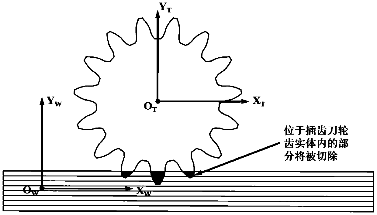
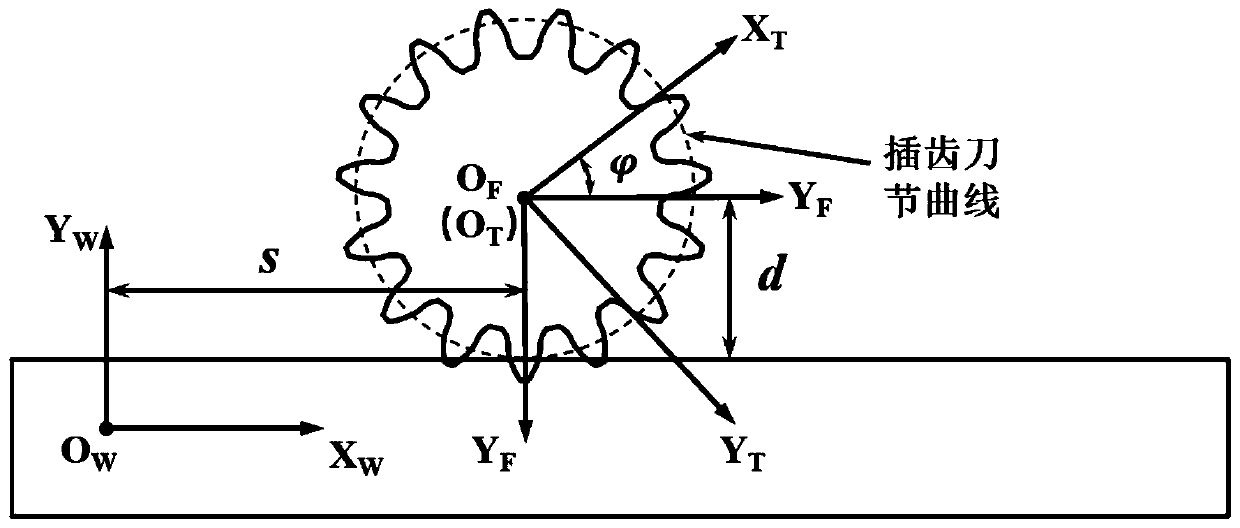
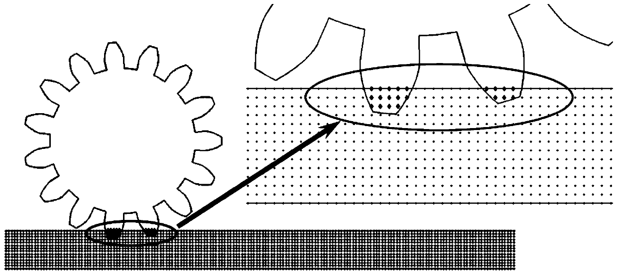

Image

  • Variable transmission ratio rack gear shaping force prediction method
  • Variable transmission ratio rack gear shaping force prediction method
  • Variable transmission ratio rack gear shaping force prediction method

Examples


Embodiment Construction

[0059] In order to make the objectives, technical solutions and advantages of the present invention clearer, the present invention will be further described in detail below with reference to the accompanying drawings and embodiments. It should be understood that the specific embodiments described herein are only used to explain the present invention, but not to limit the present invention.

[0060] Taking a variable transmission ratio rack as an example, the above method is used to predict the gear shaping force of the variable transmission ratio rack. The basic parameters of the gear shaper are shown in Table 1:

[0061] Table 1 Basic parameters of gear shaping tools

[0062]

[0063] The variable transmission ratio function formula is as follows:

[0064]

[0065] The formula for calculating the pitch curve arc length of the variable transmission ratio rack is: in is the angle of the gear shaping tool.

[0066] The method for predicting the cutting force of the ...


PUM


Abstract

The invention discloses a variable transmission ratio rack gear shaping force prediction method. The method comprises the following steps of S1, establishing a cutter gear tooth model, discretizing the cutter gear tooth model, and meanwhile, establishing a machined rack model in a workpiece coordinate system; S2, calculating a polar angle and a polar diameter from the discrete point of the rack tothe center of slotting cutters; S3, the discrete points are screened out to serve as cut points, and the number of all the screened discrete points is the size a of the cutting area; S4, judging thevertical position relation between the discrete points of all the slotting cutters and the machined surface of the machined rack; S5, screening out the discrete points at the same position on the machined surface of the machined rack, and the number of all the screened discrete points is the size b of the contact length; and S6, substituting the cutting area a and the cutting contact length b intothe metal cutting force model to finish the prediction calculation of the gear shaping force of the variable transmission ratio rack in each direction. The method provides a novel accurate calculation method for the cutting area and the cutting contact length, and accurate prediction of the gear shaping force of the variable transmission ratio rack is achieved.

Description

technical field [0001] The invention belongs to the technical field of gear shaping processing technology, and particularly relates to a method for predicting gear shaping force of a variable transmission ratio rack. Background technique [0002] The variable transmission ratio rack is a key component to balance the steering lightness and steering sensitivity during driving of the mechanical variable transmission ratio steering gear. The change of the cutting force during the gear shaping process of the variable transmission ratio rack is studied for controlling the insertion. The stability of the tooth machining process and the improvement of machining accuracy are of great significance. Due to the need to achieve a variable transmission ratio, the variable transmission ratio rack has complex and non-standard tooth profiles along the length direction, resulting in uneven cutting during the processing of the variable transmission ratio rack gear shaping process, which is pro...

Claims


Application Information

Patent Timeline
IPC IPC(8): B23F5/12B23F5/14B23F23/00B23Q17/09
CPCB23F5/12B23F5/14B23F23/00B23Q17/09B23Q17/0952
Inventor 韩星会华林徐曼
Owner WUHAN UNIV OF TECH
Learn More