Hard alloy welding circular saw blade without tooth-shaped structure

A hard alloy, toothless technology, applied in the direction of circular saws, metal sawing equipment, saw blades, etc., can solve the problems of inconsistent shape and specification, poor cutting quality, and reduced cutting efficiency, so as to increase the brazing area, Reduce the risk of breakage and reduce the effect of collapse

Pending Publication Date: 2020-05-08
陈涛
View PDF0 Cites 0 Cited by
  • Summary
  • Abstract
  • Description
  • Claims
  • Application Information

AI Technical Summary

Problems solved by technology

It can be seen from the market (1): Traditional carbide saw blades have obvious tooth-like structures. Under high-speed use, especially portable electric tools, there is a major safety risk of tooth-like structure breaking; (2) there is a hard alloy saw blade High-quality alloy particle saw blade, although it has no tooth structure, but it uses particle alloy, the shape and specification are not uniform, and the arrangement is disorderly, which will lead to reduced cutting efficiency and poor cutting quality, and more burrs

Method used


Image

  • Hard alloy welding circular saw blade without tooth-shaped structure
  • Hard alloy welding circular saw blade without tooth-shaped structure
  • Hard alloy welding circular saw blade without tooth-shaped structure

Examples


Embodiment 1

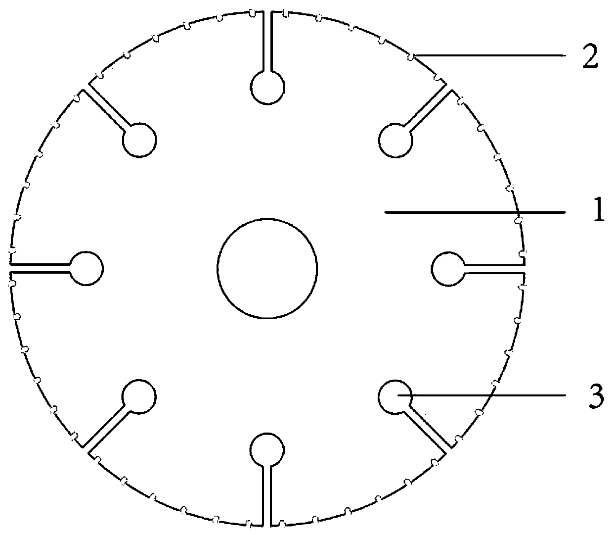
[0023] Embodiment 1: as Figure 1-2 A cemented carbide welded circular saw blade without a toothed structure is shown, including a saw blade base 1 , the saw blade base 11 is circular, has no toothed structure, and has a smooth outer edge;

[0024] A plurality of particle cutter heads 2 are arranged in order along the outer edge of the saw blade base 1, and each particle cutter head 2 can be sharpened as required.

[0025] The outer edge of the saw blade base 1 can be provided with an expansion groove 3;

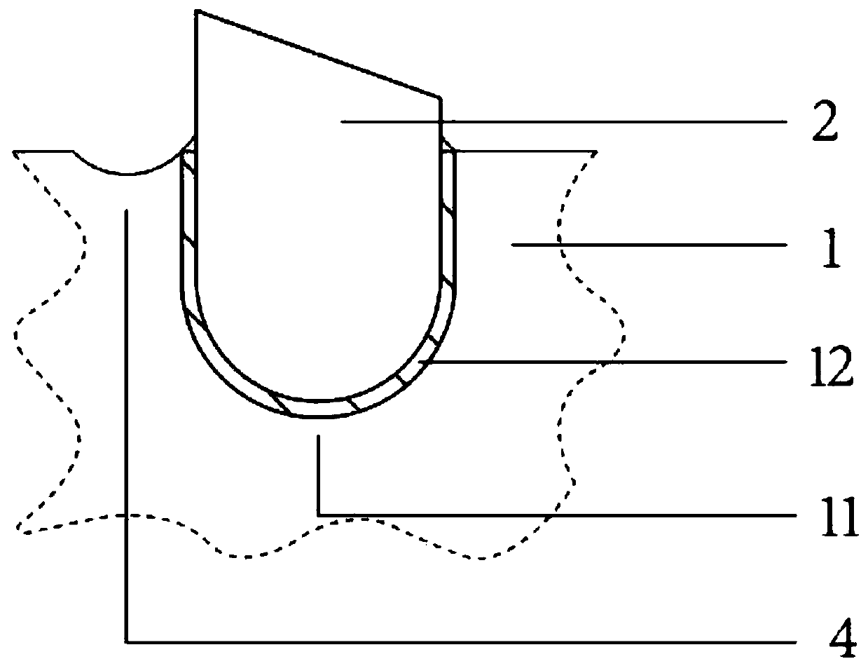
[0026] The outer edge of the saw blade base 1 has a plurality of grooves as the foundation pit 11, the particle cutter head 2 is embedded in the foundation pit 11 and welded to the saw blade base 1 by brazing material, and the brazing filler metal welding part forms a Brazing material layer 12, the lower half of described particle cutter head 2 is embedded in foundation pit 11, improves the impact resistance of particle cutter head 2 structurally, has increased the brazing ...

Embodiment 2

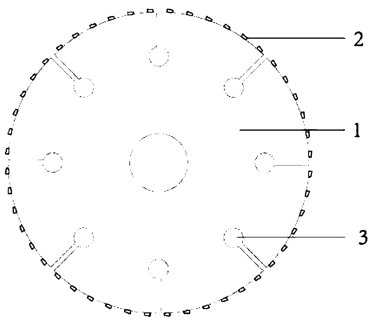
[0035] Embodiment 2: According to Figure 3-Figure 4 A cemented carbide welded circular saw blade without a toothed structure is shown, including a saw blade base 1 , the saw blade base 11 is circular, has no toothed structure, and has a smooth outer edge;

[0036] A plurality of particle cutter heads 2 are arranged in order along the outer edge of the saw blade base 1, and each particle cutter head 2 can be sharpened as required.

[0037] The outer edge of the saw blade base 1 can be provided with an expansion groove 3;

[0038] The particle cutter head 2 is welded and connected to the outer edge of the saw blade substrate 1 by means of solderless resistance butt welding, the bottom of the particle cutter head 2 is arc-shaped, and the welding position of the particle cutter head 2 is the melting point. Weld area 21.

[0039] The thickness of the saw blade base 1 is 0.5-2.5 mm, and the outer diameter of the saw blade base 1 is 50-400 mm.

[0040] The particle cutter head 2 ...


PUM

PropertyMeasurementUnit
depthaaaaaaaaaa
thicknessaaaaaaaaaa

Abstract

The invention discloses a hard alloy welding circular saw blade without a tooth-shaped structure. The hard alloy welding circular saw blade comprises a saw blade base body, the saw blade is in a circular shape without the toothless-shaped structure and the outer edge is smooth, a plurality of particle tool bits are orderly arranged along the outer circumference of the saw blade base body, and eachparticle tool bit can be subjected to edge grinding machining according to requirements. According to the hard alloy welding circular saw blade without the tooth-shaped structure, how to adjust the local structure of the saw blade can be further elaborated according to the basic principle under the conditions of welding with brazing filler metal and welding without brazing filler metal; the saw blade has a wide market prospect in portable electric tools and battery electric tools; and the safety, the accuracy and the multifunctionality of the saw blade are greatly improved.

Description

technical field [0001] The invention relates to the technical field of cutting tools, in particular to a cemented carbide welded circular saw blade with no tooth structure. Background technique [0002] At present, alloy circular saw blades are widely used as accessories of power tools in modern manufacturing and construction industries. It can be seen from the market that (1): Traditional carbide saw blades have obvious tooth-like structures. Under high-speed use, especially portable electric tools, there is a major safety risk of tooth-like structure breaking; (2) there is an existing hard alloy saw blade. High-quality alloy granulated saw blades have no tooth structure, but they are made of granulated alloys, with inconsistent shapes and specifications, and disorderly arrangement, which will lead to reduced cutting efficiency, poor cutting quality, and more burrs. [0003] In order to further improve the safety of electric tools, improve cutting efficiency, prolong cutti...

Claims


Application Information

Patent Timeline
Patent Type & Authority Applications(China)
IPC IPC(8): B27B33/08B23D61/02B28D1/04
CPCB23D61/02B27B33/08B28D1/04B23D61/025B23D61/04
Inventor 陈涛
Owner 陈涛
Why Eureka
Try Eureka