Automatic feeding and discharging injection molding machine

A technology for automatic loading and unloading and injection molding machines, which can be applied to other household appliances, optical components, household appliances, etc., and can solve problems such as the increase of injection molding equipment operators, safety risks of light guide plates, and low production efficiency, so as to improve shearing efficiency and quality effects

Inactive Publication Date: 2020-05-08
HEYUAN COE COMM TECH
View PDF7 Cites 0 Cited by
  • Summary
  • Abstract
  • Description
  • Claims
  • Application Information

AI Technical Summary

Problems solved by technology

There are two problems with this method. One is that there is a safety risk in manually removing the light guide plate with nozzle material from the injection molding equipment; the other is that manual work is required, which affects the working efficiency of the light guide plate injection molding equipment.
At the same time, the loading and unloading process of the injection molding machine is a necessary part of the process. If the loading and unloading process cannot be effectively connected, it will lead to an increase in the number of operators of the injection molding equipment, an increase in labor costs, and low production efficiency.

Method used


Image

  • Automatic feeding and discharging injection molding machine
  • Automatic feeding and discharging injection molding machine
  • Automatic feeding and discharging injection molding machine

Examples


Embodiment 1

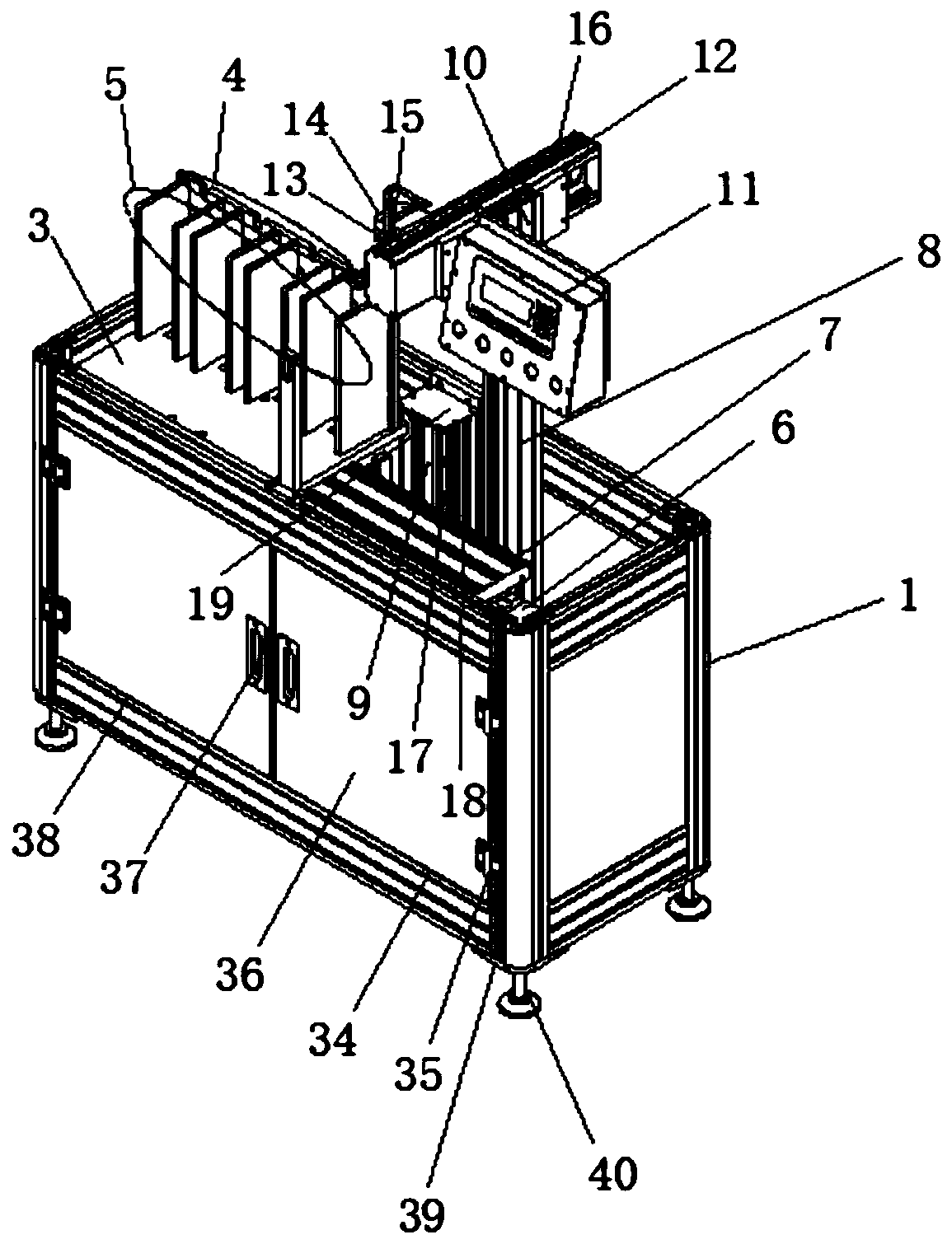
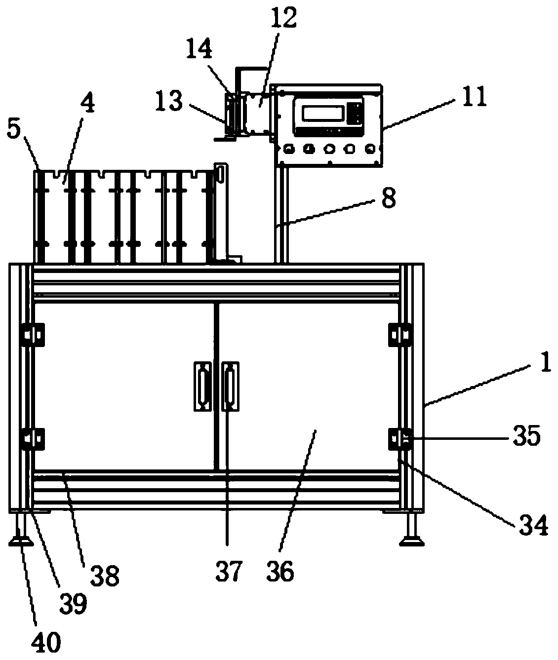
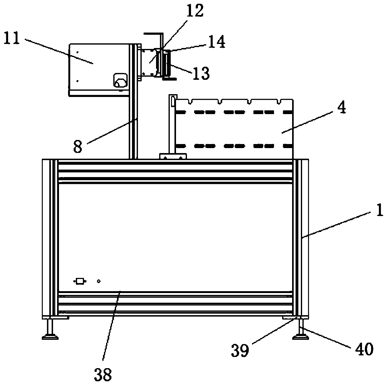
[0029] Such as Figure 1-6 As shown, the present invention provides an automatic loading and unloading injection molding machine, including a frame 1, a push cylinder 2 is arranged inside the frame 1, a support platform 3 is installed on one side of the top of the frame 1, and a baffle is provided on the top of the support platform 3 4. A side plate 5 is connected to one side of the baffle plate 4, a slide plate 6 is provided on the edge of the top side of the frame 1, and a slide rail 7 is fixed on the top of the slide plate 6, and the slide rail 7 is close to a part on the top of the frame 1. Side edge, the inboard of slide rail 7 is provided with first column 8, and one side of first column 8 is equipped with support column 9, and one side of support column 9 is equipped with second column 10, and the top of first column 8 is installed with The control panel 11, the top of the second column 10 is equipped with a clamp slide rail 12, one side of the clamp slide rail 12 is eq...


PUM


Abstract

The invention discloses an automatic feeding and discharging injection molding machine. A pushing air cylinder is mounted in a rack, a supporting table is mounted on one side of the top of the rack, abaffle is mounted on the top of the supporting table, a sliding plate is mounted on the edge of one side of the top of the rack, a first stand column is mounted on the inner side of a sliding rail, asupporting column is mounted on one side of the first stand column, a second stand column is mounted on one side of the supporting column, a clamp sliding rail is mounted on the top of the second stand column, and a supply clamp is mounted on one side of the clamp sliding rail. A control screen is mounted on the top of the first stand column, control programming is carried out, a pushing air cylinder, an electric lifting rod and a drive motor are subjected to unified control, according to the front and back steps of an injection molding flow, the automatic work process is carried out, the feeding and discharging injection molding machine can avoid personal casualty risks caused by contact of the person and the interior of injection molding equipment, the automatic feeding and discharginginjection molding machine is provided with an automatic shear water gap device to be combined with the device, the device is applied to the feeding and discharging injection molding machine, and the water gap shearing efficiency and quality are improved.

Description

technical field [0001] The invention relates to the field of light guide plate injection molding equipment, in particular to an automatic loading and unloading injection molding machine. Background technique [0002] As we all know, the injection molding of optical plastic particles into light guide plates is the field of light guide plate injection molding equipment. In the prior art, the injection-molded light guide plate with nozzle material is generally manually taken out from the injection molding machine, the light guide plate and the nozzle material are manually bent and separated, and then the light guide plate is covered with a protective film. There are two problems with this method. One is that there is a safety risk in manually removing the light guide plate with nozzle material from the injection molding equipment; the other is that manual work is required, which affects the working efficiency of the light guide plate injection molding equipment. At the same ti...

Claims


Application Information

Patent Timeline
IPC IPC(8): B29C45/18B29C45/42B29L11/00
CPCB29C45/18B29C45/4225B29L2011/00
Inventor 刘玉祥刘健
Owner HEYUAN COE COMM TECH
Why Eureka
Try Eureka