A manufacturing method for integral molding of lightweight carbon fiber chassis

A technology of integral molding and manufacturing method, applied in the direction of coating, application, household appliances, etc., can solve the problems of complex electromagnetic environment, many installation interfaces, large load, etc., to achieve the effect of many installation interfaces, compact location and light weight

Active Publication Date: 2021-11-23
CHINA ELECTRONICS TECH GRP CORP NO 14 RES INST
View PDF10 Cites 2 Cited by
  • Summary
  • Abstract
  • Description
  • Claims
  • Application Information

AI Technical Summary

Problems solved by technology

[0003] The processing unit chassis of an airborne electronic equipment product has a size of about 300×260×190mm. It needs to install more printed board components inside and power supply components outside. There are many installation interfaces, heavy load, and complex electromagnetic environment.

Method used


Image

  • A manufacturing method for integral molding of lightweight carbon fiber chassis
  • A manufacturing method for integral molding of lightweight carbon fiber chassis
  • A manufacturing method for integral molding of lightweight carbon fiber chassis

Examples


Embodiment Construction

[0047] The present invention will be further elaborated below.

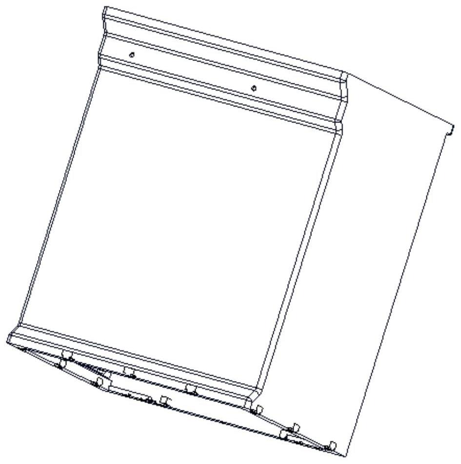
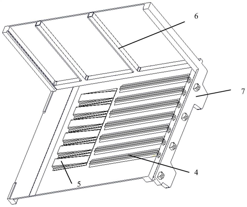
[0048] Such as Figures 1 to 2 Shown, the carbon fiber cabinet that the present invention prepares comprises guide rail 4, wedge-shaped part 5, side mounting beam 6 (as Figure 5 As shown), metal embedded parts and box body; guide rail 4 and wedge-shaped piece 5 are arranged on the left and right side walls of the box body, side mounting beams 6 are arranged on the front and rear side walls of the box body, and flange surfaces 7 are arranged at both ends of the box body , the metal embedded parts are located in the side wall of the box body, and there are installation bottom holes 3 on the metal embedded parts (such as Figure 7 shown).

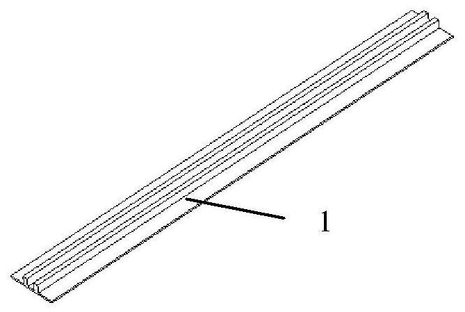
[0049] Such as image 3 As shown, the guide rail has guide rail double wings 1. Such as Figure 4 Shown, wedge-shaped piece leaves wedge-shaped piece double wing 2.

[0050] The box mold used is as Image 6 As shown, it includes rail groove 8, wedge groove 9, and side mou...


PUM

PropertyMeasurementUnit
thicknessaaaaaaaaaa
thicknessaaaaaaaaaa
thicknessaaaaaaaaaa

Abstract

The invention discloses a manufacturing method for the integral molding of a lightweight carbon fiber chassis, comprising the following contents: preforming guide rails and wedge-shaped parts; realizing threaded mounting holes; realizing threaded mounting holes through metal embedded parts, on the metal embedded parts Pre-processing the installation bottom hole, using the pre-processing installation bottom hole to accurately position on the molding surface of the cabinet mold; pre-forming the side mounting beam; cabinet layering; machining; surface metallization on the internal and external surfaces; surface three-proof. The present invention conducts reasonable split design, preforms guide rails, wedge-shaped parts, and side connecting beams, and then assembles them with box molds to carry out overall box laying and autoclave co-curing molding, which not only reduces manufacturing difficulty, but also ensures The overall rigidity requirements of the box body; more printed board components need to be installed inside the box body, power supply components need to be installed outside the box body, there are many installation interfaces, and the location is compact. Through the precise positioning technology of embedded parts, the high precision requirements of the installation position size are realized. , to ensure the connection strength.

Description

technical field [0001] The invention relates to a manufacturing method for integral molding of a chassis, in particular to a manufacturing method for integral molding of a lightweight carbon fiber chassis. Background technique [0002] The publication number is CN 105856756A, which discloses a carbon fiber composite box and its preparation method. The box in this invention has a simple structure, no connection position and assembly requirements, and is similar to a turnover box for outdoor use; this invention uses resin The import method, the material is carbon fiber and resin; the molding method is an improved method of hand lay-up molding, the performance is not high, the cost is low, and it is widely used in civilian use for parts that do not require high size and mechanical properties. [0003] The processing unit chassis of an airborne electronic equipment product has a size of about 300×260×190mm. It needs to install more printed board components inside and power suppl...

Claims


Application Information

Patent Timeline
Patent Type & Authority Patents(China)
IPC IPC(8): B29C70/34B29C70/44B29C70/54B29C70/68B29C70/70B29C70/88B29B15/14B29L31/34
CPCB29B15/14B29C70/342B29C70/443B29C70/54B29C70/681B29C70/70B29C70/88B29L2031/3481
Inventor 杨春霞王伟桂涛周吉朱永明陈旭
Owner CHINA ELECTRONICS TECH GRP CORP NO 14 RES INST
Why Eureka
Try Eureka