Color printing machine for fabrics

A printing machine and color technology, applied to printing machines, rotary printing machines, screen printing machines, etc., can solve the problems of overlapping printing, affecting the elasticity of T-shirts, and affecting printing quality, etc., to achieve fast output at the output end and high printing effect , the effect of simple structure

Active Publication Date: 2020-05-08
昆山洁宏无纺布制品有限公司
View PDF4 Cites 1 Cited by
  • Summary
  • Abstract
  • Description
  • Claims
  • Application Information

AI Technical Summary

Problems solved by technology

[0005] 1. During the transmission process, the fabric will be under tension for a long time, which will affect the elasticity of the T-shirt;
[0006] 2. The printing work is carried o

Method used


Image

  • Color printing machine for fabrics
  • Color printing machine for fabrics
  • Color printing machine for fabrics

Examples


Embodiment 1

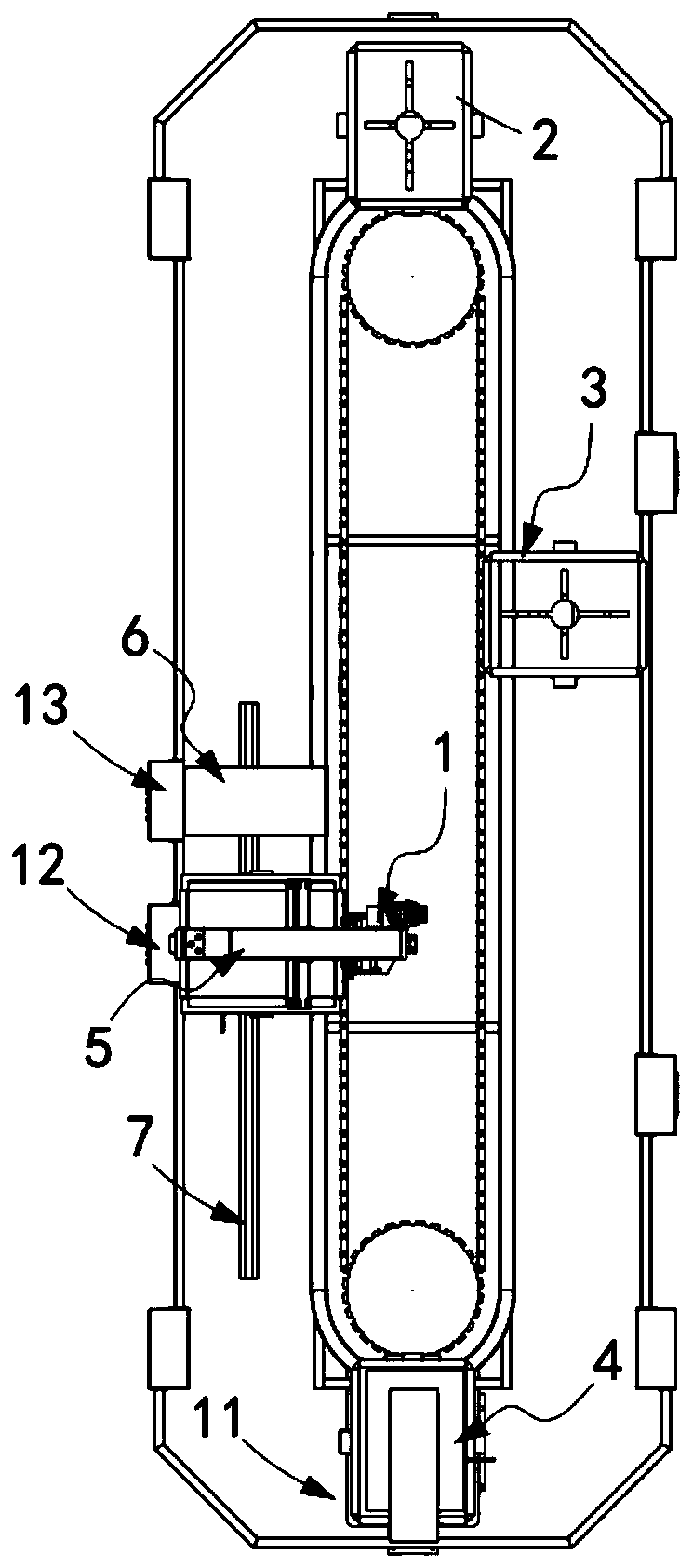
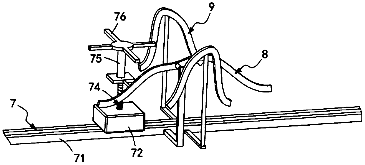
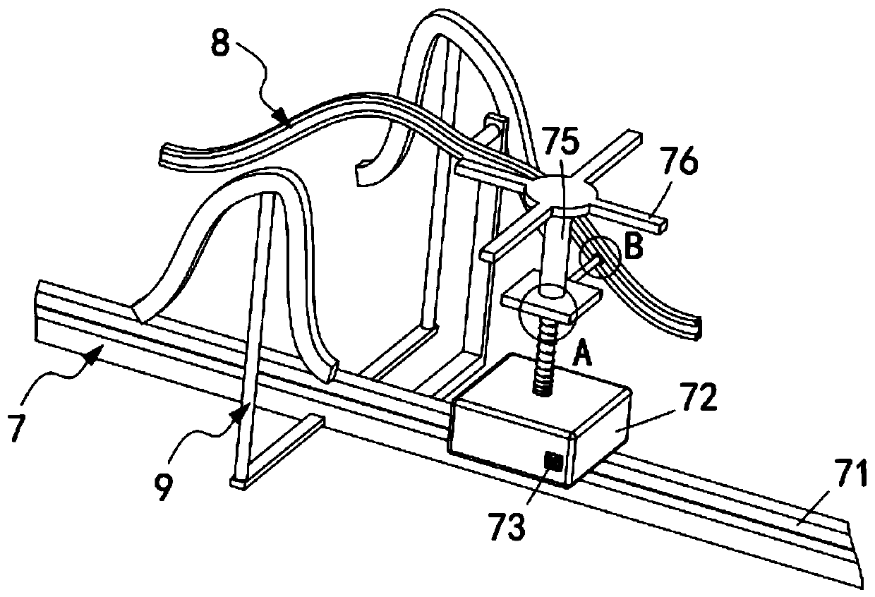
[0070] Such as figure 1 , figure 2 and image 3 As shown, a fabric color printing machine includes a printing machine 1 and several groups of cloth connecting plates 2 arranged at equal intervals along the transmission direction of the printing machine 1, and also includes a buckle mechanism 3 arranged on the cloth connecting plate 2, A flattening mechanism 4 arranged at the input end of the printing machine 1, a printing mechanism 5 arranged behind the flattening mechanism 4, and a drying mechanism 6 arranged behind the printing mechanism 5;

[0071] The printing machine 1 is sequentially provided with an input station 11, a printing station 12 and a drying station 13 along its transmission direction, the flattening mechanism 4 is located at the flattening mechanism 4, and the printing mechanism 5 is located at the printing mechanism 5 and The drying mechanism 6 is located at the drying station 13;

[0072] Below the printing mechanism 5, there is a filling mechanism 7 ma...

Embodiment 2

[0117] Such as Figure 22 , Figure 23 and Figure 24 As shown, the components that are the same as or corresponding to those in the first embodiment are marked with the corresponding reference numerals in the first embodiment. For the sake of simplicity, only the differences from the first embodiment will be described below. The difference between this embodiment two and embodiment one is:

[0118] further, such as Figure 22 , Figure 23 and Figure 24 As shown, the pressing assembly 47 includes a frame 451, a telescopic unit 452 arranged on the frame 451 and arranged vertically downward, a support rod 453 fixedly connected to the lower end of the telescopic unit 452 and connected to the The lower end of the support rod 453 is fixedly connected to the pressing plate 454, and the support rod 453 is slidingly arranged in the T-shaped groove 457 of the frame 451 through the T-shaped rod 456;

[0119] The transmission assembly 46 includes a one-way rack 461 fixedly connect...


PUM


Abstract

The invention relates to a color printing machine for fabrics. The color printing machine for the fabrics comprises a printing machine body, multiple fabric receiving plates arranged at equal intervals in the conveying direction of the printing machine body, hasp mechanisms arranged on the fabric receiving plates, a flattening mechanism arranged on an input end of the printing machine body, a printing mechanism arranged behind the flattening mechanism and a drying mechanism arranged behind the printing mechanism. A filling mechanism matched with the fabric receiving plates and a first controlmechanism for driving the filling mechanism to move up and down in the vertical direction are arranged below the printing mechanism. A second control mechanism for driving the hasp mechanisms to moveup and down in the vertical direction is arranged below the drying mechanism. The color printing machine for the fabrics solves the problem that since the fabrics are in a tensioning state for a longtime when the fabrics are conveyed, the elasticity of T-shirts is influenced.

Description

technical field [0001] The invention relates to the technical field of printing machines, in particular to a fabric color printing machine. Background technique [0002] At present, there are two types of printing screen printing, one is flat screen printing, and the other is rotary screen printing. Although the production speed of flat screen printing is not as good as that of rotary screen printing, the plate-making cost of flat screen printing is lower than that of rotary screen printing. The cycle of the printable plate is longer, and the contact time between the gray cloth and the printing screen is longer. It is suitable for fabric printing such as terry cloth, and is also more suitable for small batch fine printing. Since the popularization and application of rotary screen printing in the 1960s, it has developed rapidly. , has accounted for nearly 60% of the total fabric printing volume, and accounts for more than 90% in Western Europe. Rotary screen printing has the ...

Claims


Application Information

Patent Timeline
IPC IPC(8): B41F15/12B41F15/14B41F15/26B41F15/22B41F23/04
CPCB41F15/12B41F15/14B41F15/22B41F15/26B41F23/0443B41F23/0466
Inventor 李风丽
Owner 昆山洁宏无纺布制品有限公司
Why Eureka
Try Eureka