Clamping groove forming and cutting device for aluminum alloy clamping hoop machining and working method thereof

A technology of aluminum alloy and clamps, which is applied in metal processing and other directions, can solve the problems of easy slipping and damage of clamps, low degree of automation, and low service life, and achieve the effect of avoiding friction and collision loss, avoiding direct contact, and improving service life

Inactive Publication Date: 2019-10-08
东莞市棱锐包装材料有限公司
View PDF6 Cites 0 Cited by
  • Summary
  • Abstract
  • Description
  • Claims
  • Application Information

AI Technical Summary

Problems solved by technology

[0005] The purpose of the present invention is to solve the problem of the low working efficiency of the existing slot cutting device for processing aluminum alloy clamps; it is time-consuming and labor-intensive in use, and the degree of automation of the work is low; and the slotting and cutting of aluminum alloy clamps The precision of the work is low; and when the existing aluminum alloy clip processing clip slot cutting device adjusts the processed position and angle of the clip, the clip and the processing components on the device are not moved smoothly and smoothly, causing the clip The hoop is easy to slip and damage; the service life of the processing components on the device is low; and after the hoop is cut and grooved, it is inconvenient for the staff to collect and ship the hoop uniformly, so an aluminum alloy hoop is proposed Card slot cutting device for processing and working method thereof

Method used


Image

  • Clamping groove forming and cutting device for aluminum alloy clamping hoop machining and working method thereof
  • Clamping groove forming and cutting device for aluminum alloy clamping hoop machining and working method thereof
  • Clamping groove forming and cutting device for aluminum alloy clamping hoop machining and working method thereof

Examples


Embodiment Construction

[0053] The technical solutions of the present invention will be clearly and completely described below in conjunction with the embodiments. Apparently, the described embodiments are only some of the embodiments of the present invention, not all of them. Based on the embodiments of the present invention, all other embodiments obtained by persons of ordinary skill in the art without creative efforts fall within the protection scope of the present invention.

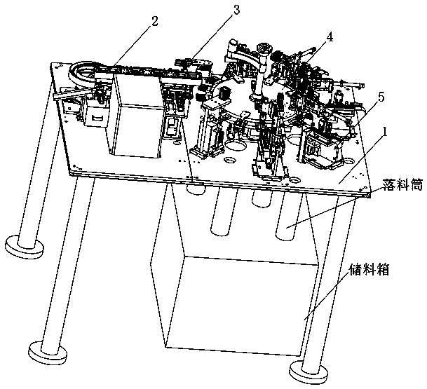
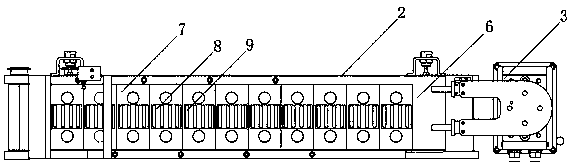
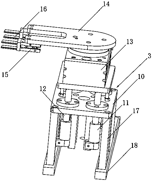
[0054] see Figure 1-14 As shown, a slot cutting device for processing aluminum alloy clamps, including a mounting base 1, a transfer table 2, a swing seat 3, a rotating disc 4 and a slotting frame 5, and the upper side of the mounting base 1 is horizontal There is a transfer table 2, one end of the transfer table 2 is provided with a swing seat 3, and one side of the swing seat 3 is provided with a circular rotary disc 4, and the edge of the rotary disc 4 is provided with several slots in an equal arc Rack 5;

[0055] Th...


PUM


Abstract

The invention discloses a clamping groove forming and cutting device for aluminum alloy clamping hoop machining. The clamping groove forming and cutting device comprises a mounting base, a conveying and receiving platform, a swing seat, a rotary adjusting disc and grooving frames, the conveying and receiving platform is horizontally arranged on one side above the mounting base, the swing seat is arranged at one end of the conveying and receiving platform, and the round rotary adjusting disc is arranged on one side of the swing seat. The clamping groove forming and cutting device has the beneficial effects that motors VII drive clamping jaws to swing and adjust, so that the distance between the two clamping jaws at the two ends of each movable clamping seat is adjusted, it is ensured that clamping hood with different shapes and widths can be clamped and fixed for cutting work of the clamping grooves by the device, and the adaptive universality is guaranteed; shifting seats are embeddedin rails of hanging rails through motors X to drive rotary cutting pieces to move forwards and backwards to adjust the positions, and the rotary cutting pieces are driven to adjust the positions up and down under the cooperation of hydraulic oil cylinders II to drive the rotary slice to move up and down, therefore, on one hand, it is ensured that the ranges of the positions, where adjustment can be achieved and the clamping groove structures can be formed and cut, of the clamping hoops are wider, and on the other hand, the position precision for forming and cutting the clamping grooves on theclamping hoops through the device is greatly improved.

Description

technical field [0001] The invention relates to a card slot cutting device, in particular to a card slot cutting device for processing an aluminum alloy clamp and a working method thereof, belonging to the application technical field of the card slot cutting device. Background technique [0002] The clamp is a connecting component that connects grooved pipe fittings, valves and pipeline fittings. It is used to connect the fast joints. The aluminum alloy clamp has the advantages of high wear resistance and corrosion resistance. More and more people of all ages. [0003] During the production and processing of aluminum alloy clamps, a groove cutting device is required to cut and slot the aluminum alloy clamps to increase the fastening and embedding points before the clamps and the parts to be fastened, so as to ensure that the clamps are fastened to the required The parts are fastened and fixed more firmly. [0004] There are still many deficiencies in the existing slotting ...

Claims


Application Information

Patent Timeline
Patent Type & Authority Applications(China)
IPC IPC(8): B23D79/00B23Q7/00
CPCB23D79/00B23Q7/00
Inventor 魏淑琼
Owner 东莞市棱锐包装材料有限公司
Why Eureka
Try Eureka