Conveying Machine Device

A conveyor and conveying path technology, applied in conveyors, mechanical conveyors, transportation and packaging, etc., can solve the problems of manufacturing cost, increased installation space, insufficient deceleration time, maintaining a certain speed, etc., and achieve space saving , Smooth and reliable conveying, the effect of simplified structure

Active Publication Date: 2014-08-06
仲西输送设备(佛山)有限公司
View PDF7 Cites 2 Cited by
  • Summary
  • Abstract
  • Description
  • Claims
  • Application Information

AI Technical Summary

Problems solved by technology

[0006] Although the above-mentioned product-and-free trolley conveyor can transport the above-mentioned brackets along a relatively steep inclined path, on the opposite side, it is composed of a power transmission chain, a power trolley, a trolley rail guiding the power trolley, a tensioning part, a large-diameter A large-scale device composed of a driving sprocket and a driven sprocket, etc., so the manufacturing cost and installation space increase (for example, refer to paragraph [0036] of Patent Document 1)
[0007] On the other hand, the conveyor device of Patent Document 2 can automatically run the carriage by gravity al

Method used


Image

  • Conveying Machine Device
  • Conveying Machine Device
  • Conveying Machine Device

Examples


Embodiment Construction

[0077] Next, embodiments of the present invention will be described in detail with reference to the drawings, but the present invention is not limited to the embodiments shown in the drawings, and includes all embodiments that satisfy the requirements described in the claims.

[0078] In this specification, along the transport direction E of the tray, the front side (downstream side) is referred to as front, the rear side (upstream side) is referred to as rear, and left and right are left and right in terms of facing forward. The figure viewed on the left serves as the main view.

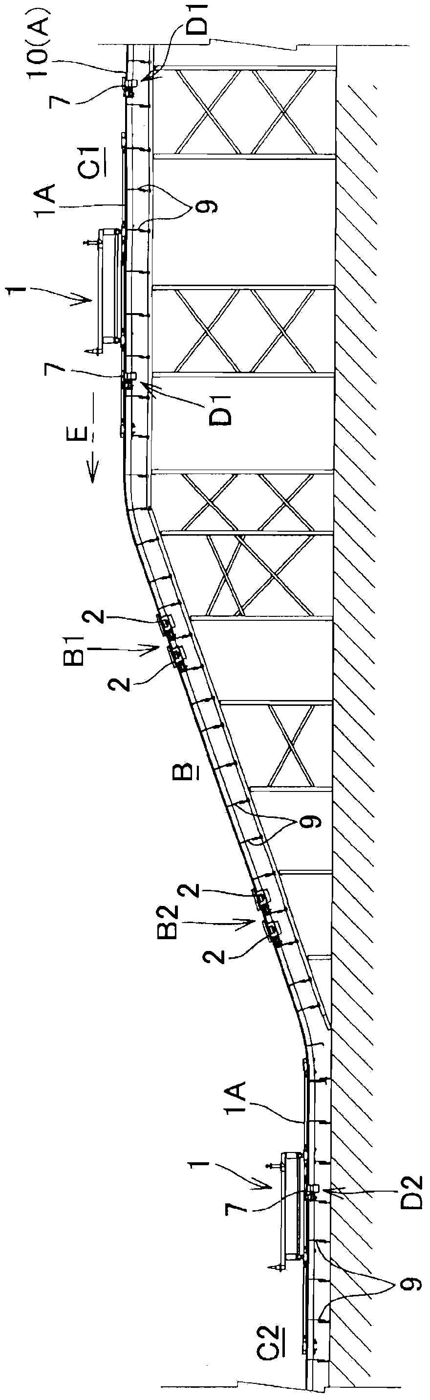
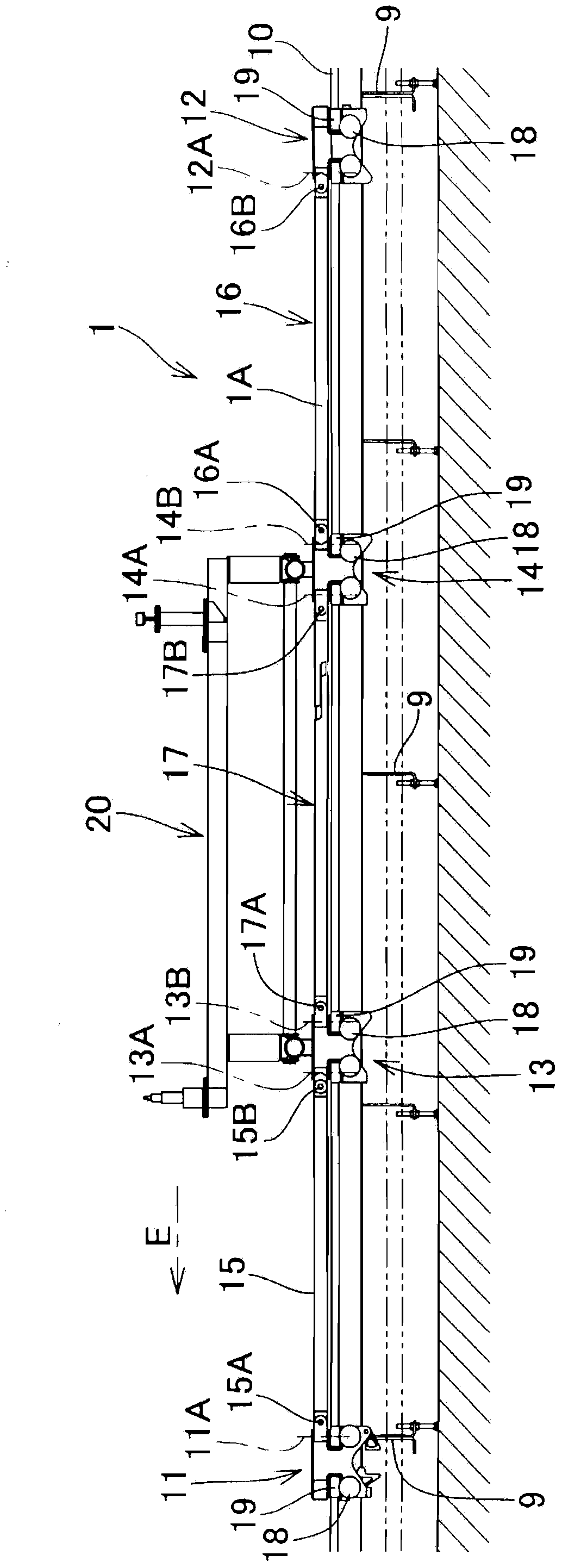
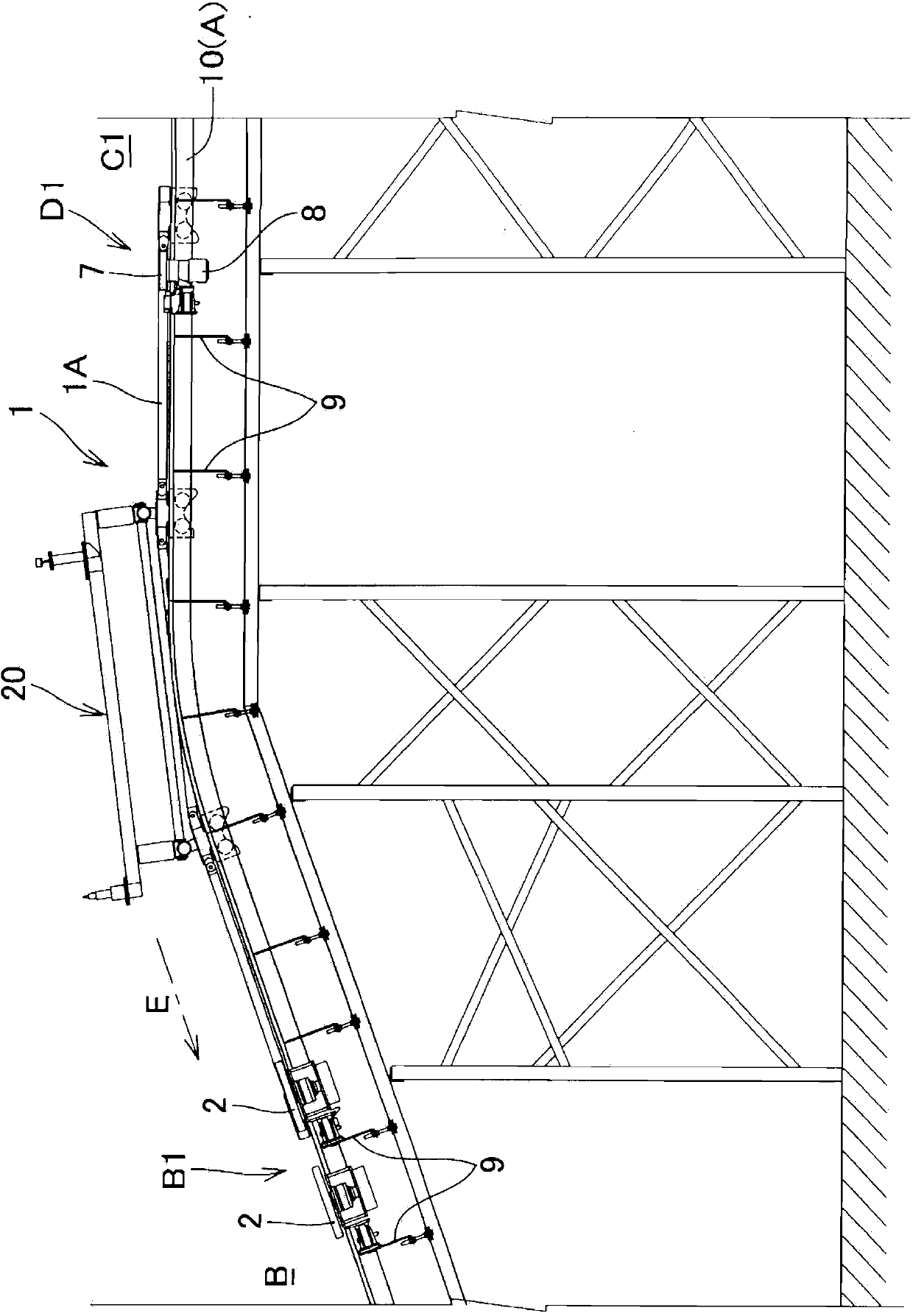
[0079] Such as figure 1 As shown in the front view of , the conveyor device according to the embodiment of the present invention is such that the carriages 1, 1, . . . , the carriages 1, 1, .

[0080] In the downward inclined path portion B, friction rollers 2 , which are friction members of non-powered braking members B1 and B2 , are in pressure contact with the friction-to-be-frictioned surface ...


PUM


Abstract

The invention provides a conveying machine device. A support frame (1) is composed of a plurality of connection rods connecting a plurality of carts in a rotary manner. The carts can move with the guidance of a guide rail (10) arranged along the conveying path (A) and can separate in the conveying direction (E). A continuous to-be-fricated face (A) is formed on the outer surface of the cart and the connection rods, covering the conveying direction (E). In a downstream inclined path part (B), forceless braking components (B1, B2) pressing a friction roll(2) on the to-be-fricated face (1A). At the same time, the support frame (1) is made move automaticaly through gravity. A high position horizontal path part (C1) more adjacent to the upstream side than the downstream inclined path and a low-position horizontal path part (C2) that is more adjacent to the downstream side than the downstream inclined path (B). The support frame (10) is driven through power at the same time that the driving roll (7) is pressed on the to-be-fricated face (1A).

Description

technical field [0001] The present invention relates to a conveyor device for moving a carriage along a conveyance path including a descending inclined path portion, and more particularly to a conveyor for automatically traveling the carriage by gravity without using a drive device in the descending inclined path portion device. Background technique [0002] On a production line for conveying objects with a relatively large shape and weight, such as automobiles, a conveyor device that transports the pallets on which the above-mentioned objects can move along the guide rails is used, on a relatively steep inclined path The conveyance of the above-mentioned bracket generally uses the accumulation type trolley conveyor (for example, refer to the [ 0011], [0033] and [0056]) [0003] In addition, in order to achieve cost reduction and space saving, there is a device that automatically travels the carriage by gravity without using a drive device in the downward inclined path por...

Claims


Application Information

Patent Timeline
IPC IPC(8): B65G35/06B65G13/075B61B13/12
Inventor 冈崎吉洋北口亮一
Owner 仲西输送设备(佛山)有限公司
Why Eureka
Try Eureka