
Multifunctional high-speed pantograph auxiliary pantograph lifting device

A pantograph and multi-functional technology, applied in the field of pantographs, can solve problems affecting transportation safety, catenary short circuit, etc., and achieve the effects of high reliability, low cost and simple structure

Inactive Publication Date: 2020-05-08
BEIJING CED RAILWAY ELECTRIC TECH
View PDF5 Cites 1 Cited by
  • Summary
  • Abstract
  • Description
  • Claims
  • Application Information

AI Technical Summary

Problems solved by technology

In extreme cases, when the two bows are in contact with the catenary in the two phase separation areas, if the EMU does not take effective isolation measures for the spare folding pantograph, it will short-circuit the catenary, causing serious adverse consequences affecting transportation safety

Method used


Image

  • Multifunctional high-speed pantograph auxiliary pantograph lifting device
  • Multifunctional high-speed pantograph auxiliary pantograph lifting device
  • Multifunctional high-speed pantograph auxiliary pantograph lifting device

Examples


specific Embodiment approach

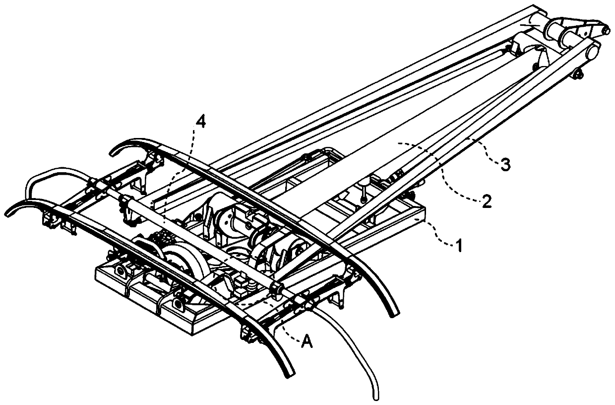
[0015] The preferred embodiment of the multifunctional high-speed pantograph auxiliary lifting device of the present invention is:

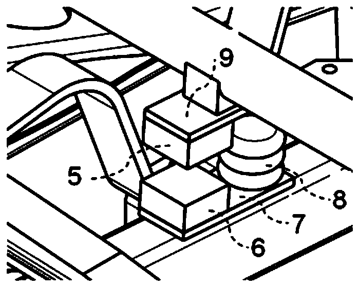
[0016] It includes a pantograph underframe, a lower arm, an upper arm, and an upper cross tube. A connection plate is fixed on the pantograph underframe. A permanent magnet material and an auxiliary bow airbag are fixed on the connection plate. The upper cross tube A connection bracket is fixed on the top, and another piece of permanent magnet material is fixed on the connection bracket;

[0017] The upper and lower positions of the two permanent magnet materials correspond to each other, and the upper part of the auxiliary bow-raising airbag corresponds to the position of the connecting bracket.

[0018] In the falling bow state, the two permanent magnet materials rely on magnetic force to adsorb and fit together;

[0019] During the bow-raising process, the auxiliary bow-raising airbag is inflated to push up the connecting bracket.

[0020] T...

specific Embodiment

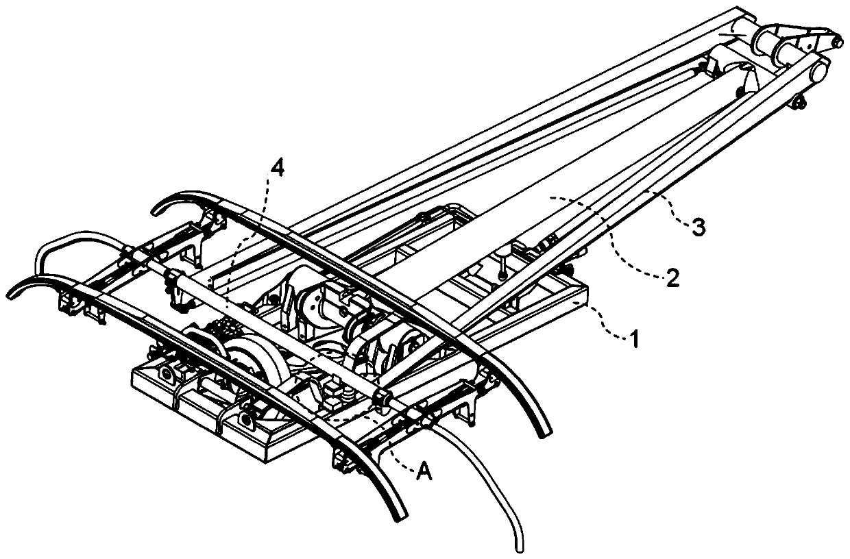
[0028] Such as figure 1 As shown, a multifunctional high-speed pantograph auxiliary lifting device is composed of a pantograph chassis 1, an upper arm 3, an upper cross tube 4, a permanent magnet material 5, a permanent magnet material 6, a connecting plate 7, and an auxiliary bow lifting airbag 8 and connecting bracket 9 and other parts.

[0029] The multifunctional high-speed pantograph auxiliary lifting device is divided into upper and lower parts: the lower part installs and fixes the permanent magnet material 6 and the auxiliary lifting air bag 8 on the pantograph chassis 1 through the connecting plate 7; In the half part, the connecting bracket 9 is welded to the upper cross pipe 4 of the upper arm 3 of the pantograph, and the permanent magnet material 5 is fastened to the connecting bracket 9 by bolts.

[0030] Among them, the permanent magnet material 5 and the permanent magnet material 6 can be aligned and bonded in the state of the pantograph falling, and the auxili...


PUM


Abstract

The invention discloses a multifunctional high-speed pantograph auxiliary pantograph lifting device. The device comprises a pantograph bottom frame, a lower arm, an upper arm and an upper cross pipe,a connecting plate is fixed to the pantograph bottom frame, a permanent magnet material and an auxiliary pantograph lifting air bag are fixed to the connecting plate, a connecting support is fixed tothe upper cross pipe, and another permanent magnet material is fixed to the connecting support. The upper portions and the lower portions of the two permanent magnet materials correspond to each other, and the upper portion of the auxiliary pantograph lifting air bag corresponds to the connecting support. The device has the characteristics of the simple structure, the low cost, the high reliability and the like, solves the problems that the high-speed pantograph of the existing motor train unit cannot be lifted and the pantograph floats up when the pantograph is used as a standby folding pantograph to operate, can ensure the operation order, and improves the application efficiency of the motor train unit.

Description

technical field [0001] The invention relates to a pantograph technology, in particular to a multifunctional high-speed pantograph auxiliary lifting device. Background technique [0002] The pantograph acts as a two-way transmission hub between the catenary and the train: it obtains electrical energy from the catenary to supply power to the entire train electrical system, and at the same time converts the kinetic energy of the train into electrical energy and feeds it back to the catenary through the regenerative braking system of the train For use by other online trains. [0003] During the operation and maintenance of the pantographs of high-speed EMUs, failures of the pantographs to fail to raise and receive current often occur due to reasons such as low initial lifting force, adhesion of the support buffer rubber stack to the bow body, and freezing of ice and snow. [0004] During the high-speed operation of the high-speed EMU pantograph, due to the high speed of operati...

Claims


Application Information

Patent Timeline
Patent Type & Authority Applications(China)
IPC IPC(8): B60L5/32
CPCB60L5/32
Inventor 马德彪苏安社于金朋高文斌吴荣平徐玉峰
Owner BEIJING CED RAILWAY ELECTRIC TECH
Learn More