Film cutoff device

A film cutting and cutting knife technology, which is applied in thin material processing, transportation and packaging, metal processing, etc., can solve problems such as troublesome control, cumbersome actions, and complex structures, and achieve the effect of simple structure, flexible and reliable actions

Pending Publication Date: 2020-05-08
大连橡胶塑料机械有限公司
View PDF0 Cites 1 Cited by
  • Summary
  • Abstract
  • Description
  • Claims
  • Application Information

AI Technical Summary

Problems solved by technology

[0003] The present invention aims at the problem that the cutting device is installed outside the friction roller in the prior art, resulting in complex st

Method used


Image

  • Film cutoff device
  • Film cutoff device
  • Film cutoff device

Examples


Embodiment 1

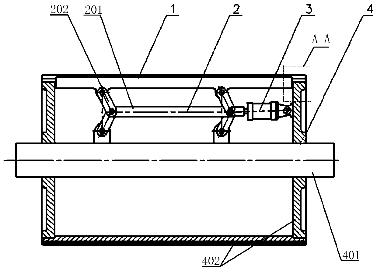
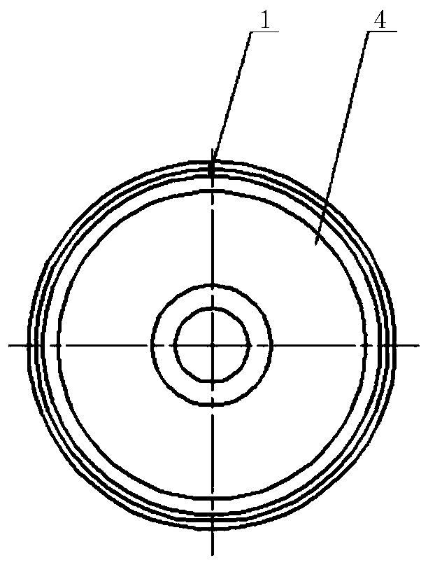
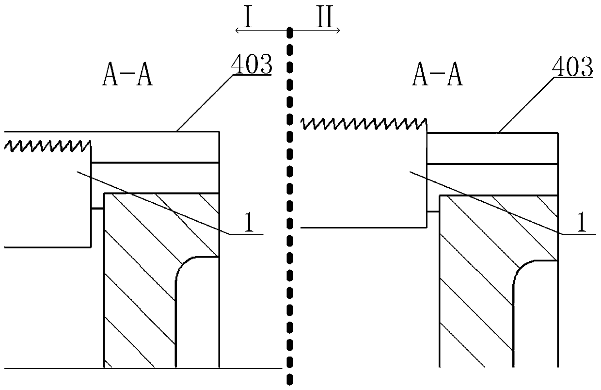
[0018] Such as figure 1 , figure 2 A film cutting device is shown, and the film cutting device includes a cutting knife 1 , a cutting knife lifting mechanism 2 , a cutting knife lifting power unit 3 and a friction roller 4 . The cutting knife 1 is installed inside the rubbing roller 4 . The friction roller 4 includes a roller shaft 401 and a roller 402 coaxially fixedly installed on the outside of the roller shaft 401. The circumferential surface of the roller 402 is provided with an axial opening for providing the radial displacement space of the cutting knife 1, and Limit displacement in other directions.

[0019] The cutting knife lifting mechanism 2 includes a connecting rod A201 and a connecting rod B202. There are four connecting rods B202, and any end of the connecting rod B202 is articulated on the connecting rod A201. The rotation of each connecting rod B202 The planes are parallel to each other; the free end of a part of the connecting rod B202 is articulated on ...

Embodiment 2

[0025] A film cutting device, comprising a cutting knife 1 , a cutting knife lifting mechanism 2 , a cutting knife lifting power unit 3 and a friction roller 4 . The friction roller 4 includes a roller shaft 401 and a roller 402 coaxially fixedly installed on the outside of the roller shaft 401. The circumferential surface of the roller 402 is provided with an axial opening for providing the radial displacement space of the cutting knife 1, and Limit displacement in other directions.

[0026] The cutting knife lifting mechanism 2 includes a connecting rod A201 and a connecting rod B202. There are six connecting rods B202 in total, and any end of the connecting rod B202 is movably hinged on the connecting rod A201. The rotation of each connecting rod B202 The planes are parallel to each other; the free end of a part of the connecting rod B202 is articulated on the roller shaft 401, and the free end of the other part of the connecting rod B202 is articulated on the cutting knife...


PUM


Abstract

The invention discloses a film cutoff device, and belongs to the technical field of film winding cutoff. The film cutoff device comprises a cutoff knife, a cutoff knife lifting mechanism, a cutoff knife lifting power unit and a friction roller. The cutoff knife is installed inside the friction roller. When the cutoff knife lifting power unit stretches out, the cutoff knife lifting power unit drives the cutoff knife to stretch out of the peripheral surface of a roller cylinder through the cutoff knife lifting mechanism, and a film is cut off. After cutoff operation is accomplished, the cutoff knife lifting power unit draws back, the cutoff knife lifting power unit drives the cutoff knife to draw back to the interior of the peripheral surface of the roller cylinder through the cutoff knife lifting mechanism. The film cutoff device has the beneficial effects that the cutoff knife is installed inside the friction roller, can stretch out of the friction roller surface and can draw back to the interior of the friction roller. The film cutoff device is simple in structure, flexible and reliable in motion and agile to control.

Description

technical field [0001] The invention belongs to the technical field of film winding and cutting, and in particular relates to a film cutting device. Background technique [0002] The cutting device of the existing film coiler is basically outside the friction roller. When cutting the film, it is necessary to separate the film wrapped on the friction roller from the friction roller after the cutting knife rotates around the friction roller to a certain position. , and then cut the film in the air to prevent the cutting knife from hurting the friction roller. Its structure is relatively complicated, the action is relatively loaded down with trivial details, and control is also very troublesome. Contents of the invention [0003] The present invention aims at the problem that the cutting device is installed outside the friction roller in the prior art, resulting in complex structure, cumbersome action and troublesome control, and provides a film cutting device with simple st...

Claims


Application Information

Patent Timeline
IPC IPC(8): B65H35/06B26D1/08
CPCB26D1/085B65H35/06
Inventor 赵辉
Owner 大连橡胶塑料机械有限公司
Why Eureka
Try Eureka