Grouting device for road bridge construction

A technology of bridge construction and grouting device, applied in the direction of bridges, bridge materials, bridge construction, etc., can solve the problems of affecting the efficiency of grouting, agglomeration and solidification of the slurry, etc., to ensure safety, high quality of discharge, safety high sex effect

Inactive Publication Date: 2020-05-08
河南邦特威机电设备有限公司
View PDF7 Cites 4 Cited by
  • Summary
  • Abstract
  • Description
  • Claims
  • Application Information

AI Technical Summary

Problems solved by technology

[0004] The purpose of the present invention is to solve the shortcomings in the prior art that there is no certain mixing and filtering device for cement and concrete, which may cause the slurry to agglomerate and solidify, which will greatly affect the efficiency of grouting, and propose a road bridge Grouting device for construction

Method used


Image

  • Grouting device for road bridge construction
  • Grouting device for road bridge construction
  • Grouting device for road bridge construction

Examples


Embodiment 1

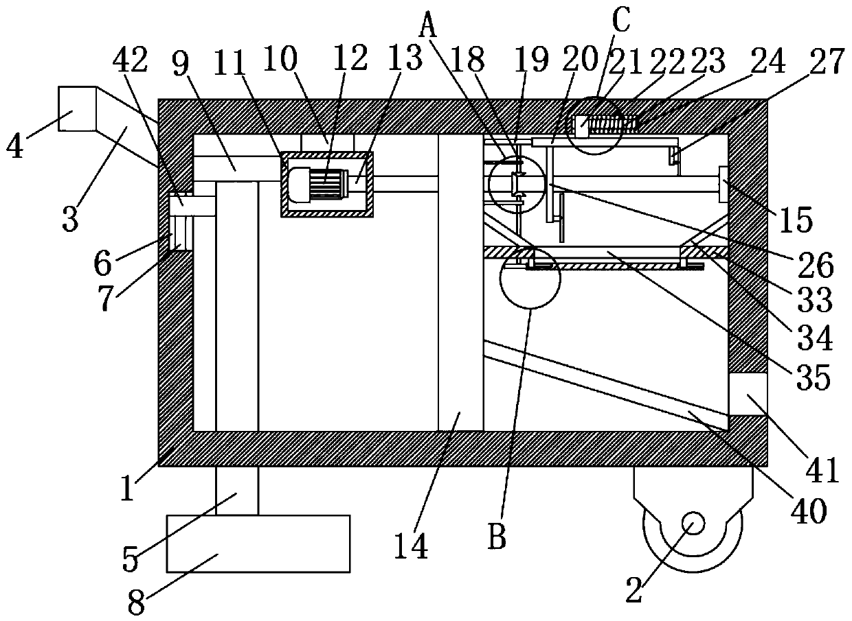
[0027] refer to Figure 1-5 , a grouting device for road and bridge construction, comprising a box body 1, a bottom wheel 2 is fixedly installed on the bottom of the box body 1, two fixed plates 3 are fixedly fixedly installed on one side of the box body 1, and two fixed plates 3 are fixed on the bottom of the box body 1. The same handle 4 is fixedly installed, and a pillar 5 is slidably installed on one side of the inner wall of the box body 1. A bottom plate 8 is fixedly installed on one end of the pillar 5, and a circuit board 9 is fixedly installed on the other end of the pillar 5. The top inner wall of the box body 1 A drive motor 12 is fixedly installed on the top, and one end of the drive shaft 13 is fixedly installed on the output shaft of the drive motor 12. Plate 14, one end of the transmission rod 18 is rotatably installed on the drive shaft 13, the transmission rod 18 is rotatably mounted on one side of the partition 14, the other end of the transmission rod 18 is ...

Embodiment 2

[0038] refer to Figure 1-5 A grouting device for road and bridge construction, comprising a box body 1, the bottom of the box body 1 is fixedly equipped with a bottom wheel 2, which facilitates the movement of the whole device, and one side of the box body 1 is symmetrically fixedly installed with two fixed plates 3, The same handle 4 is fixedly installed on the two fixed plates 3, which is convenient for the control of the device. A pillar 5 is slidably installed on one side of the inner wall of the box body 1, and a bottom plate 8 is fixedly installed on one end of the pillar 5, and the other end of the pillar 5 is fixed. A circuit board 9 is installed, a drive motor 12 is fixedly installed on the top inner wall of the box body 1, an end of the drive shaft 13 is fixedly installed on the output shaft of the drive motor 12, and the other end of the drive shaft 13 is rotatably installed on one side of the box body 1. On the side inner wall, a partition 14 is fixedly installed ...


PUM


Abstract

The invention belongs to the technical field of bridge construction equipment, in particular to a grouting device for road bridge construction. In the prior art, cement and concrete are not provided with a certain stirring and filtering device, the slurry caking and solidification can be possibly caused, and the grouting efficiency can be greatly influenced. In the proposed scheme, the device comprises a box body, bottom wheels are fixedly installed at the bottom of the box body, two fixed plates are symmetrically and fixedly mounted on one side of the box body, the same handle is fixedly installed on the two fixed plates, a supporting column is slidably installed on the inner wall of one side of the box body, a bottom plate is fixedly installed at one end of the supporting column, a circuit board is fixedly installed at the other end of the supporting column, a driving motor is fixedly installed on the inner wall of the top of the box body, and one end of a driving shaft is fixedly installed on an output shaft of the driving motor. According to the device, slurry can be ensured not to be caked and solidified, use is convenient, the discharging quality is high and guaranteed, and the safety of the device is high.

Description

technical field [0001] The invention relates to the technical field of bridge construction equipment, in particular to a grouting device for road and bridge construction. Background technique [0002] Bridges generally refer to structures erected on rivers, lakes, and seas to allow vehicles and pedestrians to pass smoothly. In order to adapt to the modern high-speed development of the transportation industry, bridges are also extended to cross mountains, poor geology, or meet other traffic needs to make traffic more convenient. In the construction of buildings and modern bridges, it is often necessary to use grouting machines to pour cement and concrete, which can improve the efficiency of road and bridge construction. [0003] Most of the existing grouting devices for road and bridge construction are to add the mixed cement and concrete into the grouting device. They lack mixing equipment. In actual use, the cement and concrete added to the grouting device may be left for t...

Claims


Application Information

Patent Timeline
Patent Type & Authority Applications(China)
IPC IPC(8): E01D21/00B28C5/48E01D101/24
CPCB28C5/485E01D21/00E01D2101/24
Inventor 陈云
Owner 河南邦特威机电设备有限公司
Why Eureka
Try Eureka