
Floating type transmission mechanism and micro pump

A transmission mechanism, floating technology, applied in the field of plunger pump, to achieve the effect of smooth connection movement and eliminating the accumulated stress of transmission

Inactive Publication Date: 2020-05-08
中船重庆液压机电有限公司
View PDF5 Cites 1 Cited by
  • Summary
  • Abstract
  • Description
  • Claims
  • Application Information

AI Technical Summary

Problems solved by technology

This product has always been imported from abroad. At present, this type of micropump has a large demand in the domestic market, but the country is still in the research and development stage, so it is urgent to develop a small volume and large output micro displacement suitable for robots and intelligent equipment. Piston pump to fill the domestic gap in this field

Method used


Image

  • Floating type transmission mechanism and micro pump
  • Floating type transmission mechanism and micro pump
  • Floating type transmission mechanism and micro pump

Examples


Embodiment Construction

[0023] Below, the substantive features and advantages of the present invention will be further described in conjunction with examples, but the present invention is not limited to the listed examples.

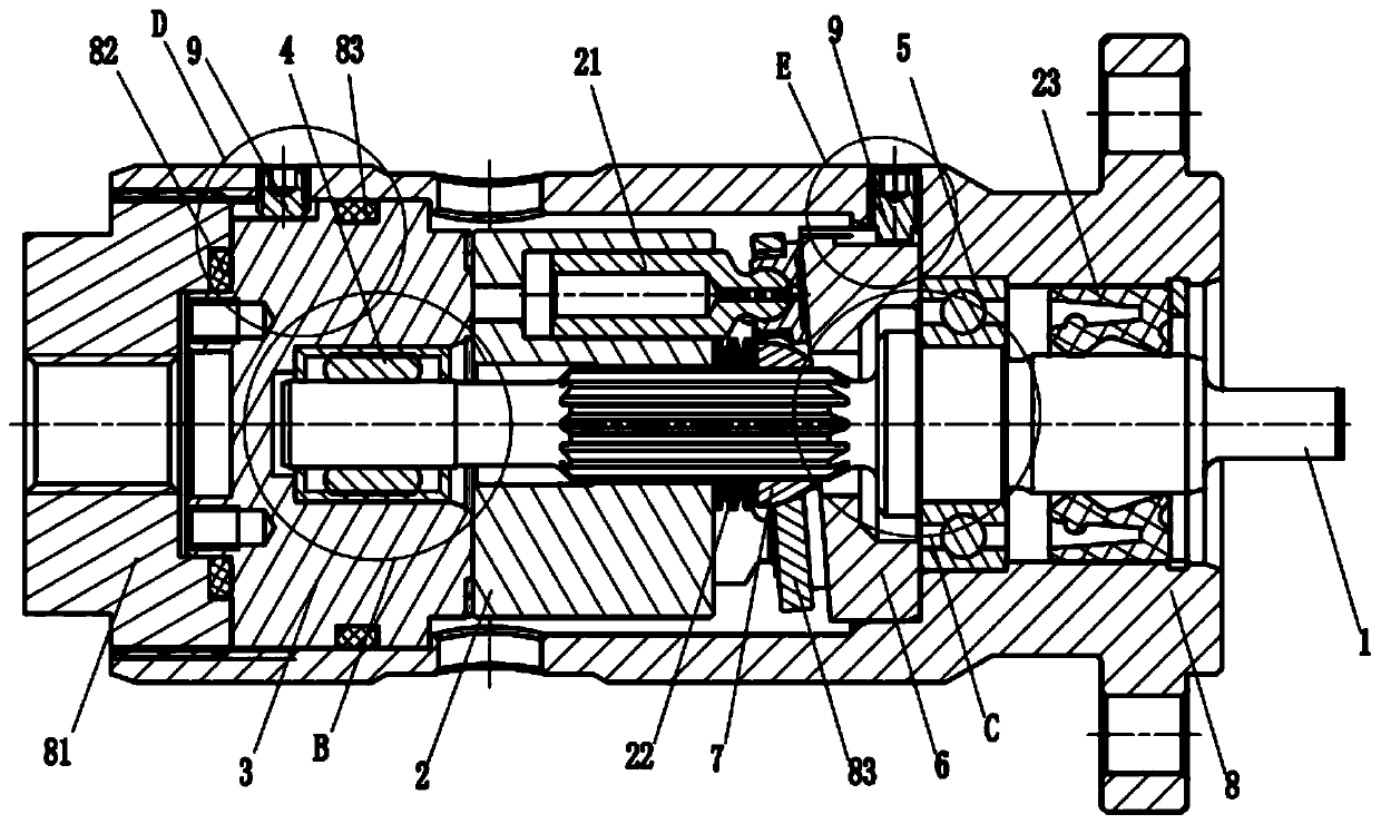
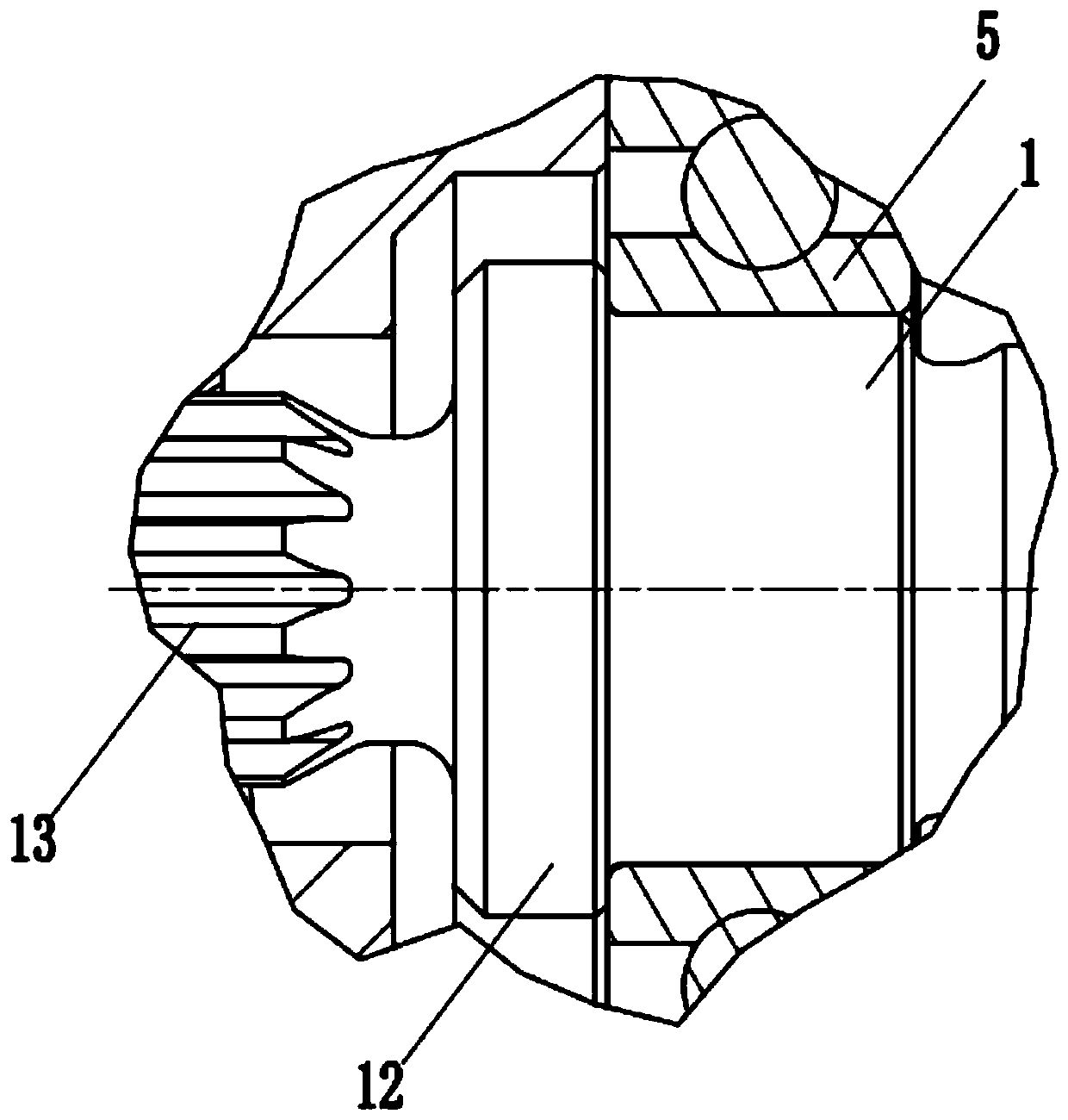
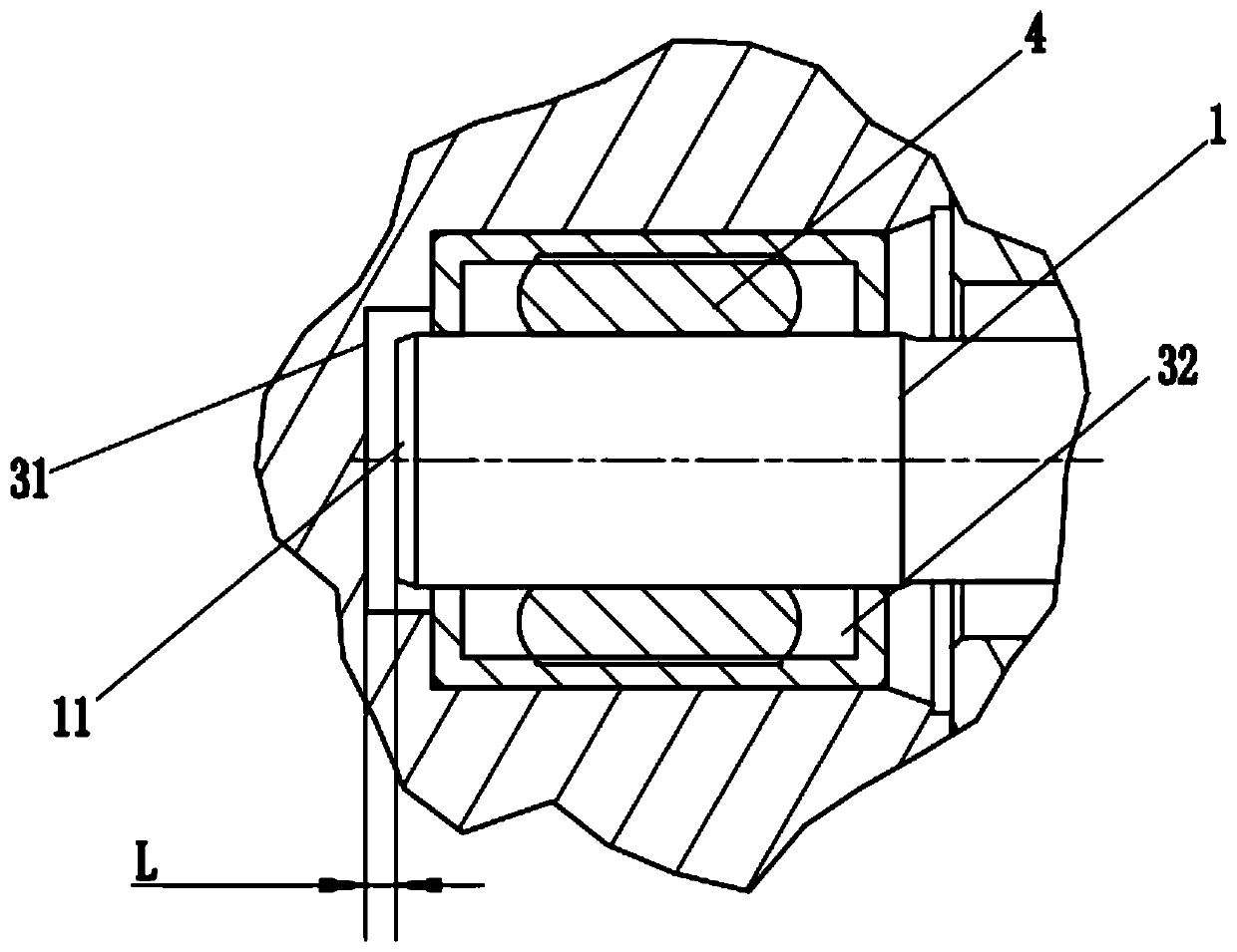
[0024] Such as Figure 1 to Figure 5 As shown, a floating transmission mechanism of this embodiment is applied to a micro-displacement plunger pump, that is, a micro pump. The floating transmission mechanism includes a transmission shaft 1, and the transmission shaft 1 is connected to the cylinder body 2 through a spline. The end portion 11 of the transmission shaft 1 is located in the distribution plate 3, and there is a floating gap L between the end portion 11 and the inner end surface 31 of the distribution plate 3. When the transmission shaft 1 rotates, it is within the axial range allowed by the floating gap L Can be floated. In the above technical solution, the transmission shaft 1 and the cylinder body 2 are driven by drum splines to convert the hydraulic pressure into...


PUM


Abstract

The invention relates to a floating type transmission mechanism and a micro pump. The floating type transmission mechanism comprises a transmission shaft. The transmission shaft is connected with a cylinder body through a spline. The tail end of the transmission shaft is located in a flow distributing plate. A floating gap is formed between the tail end of the transmission shaft and the inner endface of the flow distributing plate. During transmission of the transmission shaft, floating can be performed within the axial range permitted by the floating gap. The transmission stress caused by the transmission of the spline and the radial gap of the transmission of the spline can be eliminated, the transmission shaft of the micro pump can float at the small amplitude in the axial direction, the transmission cumulative stress within a certain range can be eliminated, and the connection movement of the transmission shaft and other components is more stable and efficient.

Description

technical field [0001] The invention relates to the technical field of small displacement plunger pumps, in particular to a floating transmission mechanism and a micropump. Background technique [0002] The plunger pump is a common power drive component in the hydraulic industry. It is widely used in various industries such as aerospace, shipbuilding, marine equipment, mining metallurgy, energy, and intelligent equipment. It has a large market demand and a wide range of applications. The division of labor, artificial intelligence, micro-robots, etc. have increased the demand for plunger pumps that are increasingly lightweight, intelligent, and centralized. Traditional plunger pumps have gradually been unable to meet the increasing market demand for micro-piston pumps in various industries. However, at present, there are almost only a few foreign brands of miniature plunger pumps in the domestic market, and no self-owned brand miniature plunger pumps have been put on the mark...

Claims


Application Information

Patent Timeline
Patent Type & Authority Applications(China)
IPC IPC(8): F04B1/2014F04B1/2035F04B1/2078F04B1/2042
CPCF04B1/2014F04B1/2035F04B1/2042F04B1/2078
Inventor 车芳芳黄天明冉益明
Owner 中船重庆液压机电有限公司
Learn More