
An automatic air-drying system and method for respiratory support equipment and respiratory support equipment

A technology that supports equipment and is automatic, applied in respirator, lighting and heating equipment, drying and other directions to achieve safer and healthier use, reduce the risk of bacterial growth, and ensure the effect of drying

Inactive Publication Date: 2021-10-01
HUNAN MICOME ZHONGJIN MEDICAL SCI & TECH DEV CO LTD
View PDF8 Cites 0 Cited by
  • Summary
  • Abstract
  • Description
  • Claims
  • Application Information

AI Technical Summary

Problems solved by technology

[0008] Thereby the air-drying technology after using in the existing respiratory support equipment has deficiencies, and needs to be improved and improved

Method used

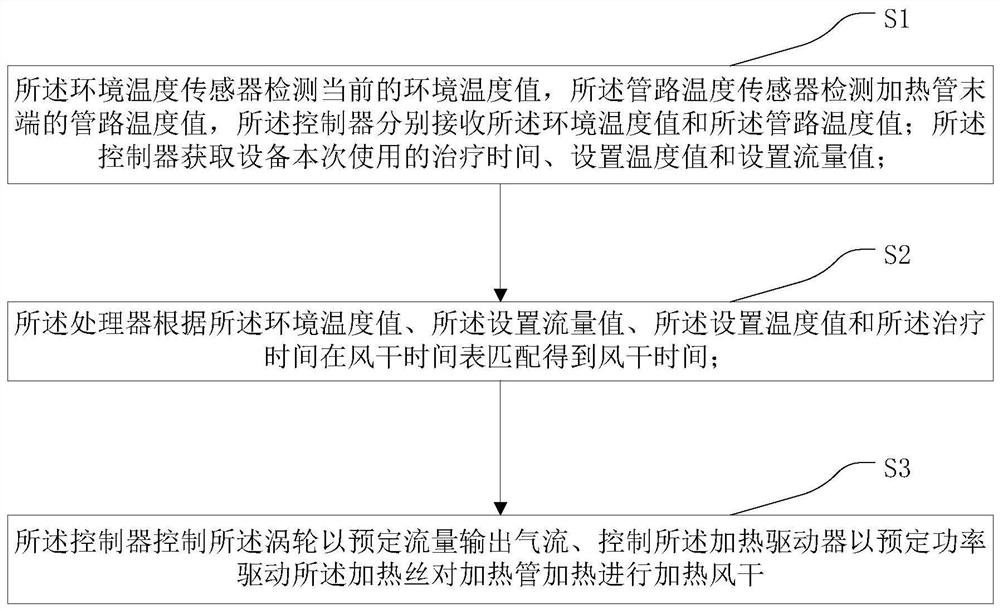
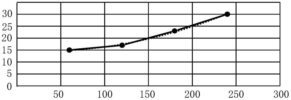

Image

  • An automatic air-drying system and method for respiratory support equipment and respiratory support equipment
  • An automatic air-drying system and method for respiratory support equipment and respiratory support equipment
  • An automatic air-drying system and method for respiratory support equipment and respiratory support equipment

Examples


Embodiment 1

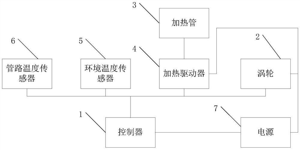
[0040]The present invention provides an automatic air-drying system for respiratory support equipment, comprising: a controller 1, a turbine 2, a heating tube 3, a heating driver 4, an ambient temperature sensor 5, a pipeline temperature sensor 6 and a power supply 7; the air outlet of the turbine 2 Connected with the heating pipe 3 through a pipeline, the ambient temperature sensor 5 is installed at the air inlet of the turbine 2; the pipeline temperature sensor 6 is installed at the airflow output end of the heat pipe; the The heating pipe 3 has a heating wire, and the heating wire is connected to the heating driver 4; the turbine 2, the ambient temperature sensor 5, the pipeline temperature sensor 6 and the heating driver 4 are respectively connected to the control connected to the controller 1; the power supply 7 is connected to the controller 1, the turbine 2, and the heating driver 4 respectively. Specifically, the controller 1 is a processor commonly used in the art (MC...

Embodiment 2

[0067] The invention also provides a respiratory support device, including an automatic air-drying system for the respiratory support device.

[0068] The respiratory support device of the present invention is preferably a high-flow humidified oxygen therapy instrument, which is mainly composed of a high-flow humidified oxygen therapy instrument main body, a water box, a heating plate and an external pipeline, wherein the turbine 2 belongs to the main part, and the water box and The heating plate constitutes the main structure of the humidifier, and the external pipeline mainly refers to the heating pipeline and nasal oxygen tube used by the user when using the household humidified oxygen therapy device. A temperature sensor is provided at the air inlet to detect the current ambient temperature. After the air and oxygen are mixed, they enter the water box after passing through the turbine 2, and the heating plate continues to heat, taking away part of the water vapor, and then...


PUM


Abstract

The invention relates to an automatic air-drying system and method for respiratory support equipment and respiratory support equipment. An automatic air-drying system for respiratory support equipment, comprising: a controller, a turbine, a heating tube, a heating driver, an ambient temperature sensor, a pipeline temperature sensor, and a power supply; the air outlet of the turbine is connected to the heating tube through a pipeline, and the The ambient temperature sensor is installed at the air inlet of the turbine; the pipeline temperature sensor is installed at the airflow output end of the heat pipe; the heating pipe has a heating wire, and the heating wire is connected to the heating pipe. The driver is connected; the turbine, the ambient temperature sensor, the pipeline temperature sensor and the heating driver are respectively connected to the controller; the power supply is respectively connected to the controller, the turbine, and the heating driver connect. The invention can automatically heat and air-dry the external pipeline after the patient uses it, so as to reduce the risk of bacterial growth.

Description

technical field [0001] The invention relates to the field of air-drying of respiratory support equipment, in particular to an automatic air-drying system and method for respiratory support equipment and the respiratory support equipment. Background technique [0002] Respiratory support technology is an important means of treating respiratory failure. Nasal high-flow oxygen humidification therapy (referred to as high-flow oxygen therapy, High-Flow Nasal Cannula, HFNC) is a new type of respiratory support technology. The warmed and humidified gas, with a flow rate of 30-60L / Min or above, achieves the purpose of delivering a stable concentration of oxygen, flushing the dead space of the upper airway, and generating a certain positive end-expiratory airway pressure, and the patient's tolerance is good . [0003] The current high-flow oxygen therapy products are mainly medical products. For some patients with mild symptoms, hospitalization will generate high costs and occupy un...

Claims


Application Information

Patent Timeline
Patent Type & Authority Patents(China)
IPC IPC(8): F26B3/02F26B21/00F26B21/10F26B25/00A61M16/00
CPCA61M16/00F26B3/02F26B21/001F26B21/004F26B21/10F26B25/00
Inventor 戴征李蒙
Owner HUNAN MICOME ZHONGJIN MEDICAL SCI & TECH DEV CO LTD
Learn More