
Gas stove control method based on pressing type rotary knob

A control method and technology for gas stoves, applied in the field of gas stoves, can solve problems such as reduced convenience experience, reduced safety, fire occurrence, etc., and achieve the advantages of reducing unnecessary gas air-burning time, improving operation convenience, and reducing mechanical wear and tear. Effect

Active Publication Date: 2019-08-16
杨永生
View PDF4 Cites 3 Cited by
  • Summary
  • Abstract
  • Description
  • Claims
  • Application Information

AI Technical Summary

Problems solved by technology

However, in actual use, different recipes are used, and the safety will be reduced. For example, for some recipes, the "10-minute automatic fire-off time" is likely to cause carbonization and combustion of ingredients and cause a fire, and "10-minute automatic fire-off time" After the fire, the knob needs to be turned off to re-rotate the knob to catch fire" will increase the number of rotations of the knob and cause the cock valve to wear, resulting in an increase in air leakage; in addition, the convenience experience will be correspondingly reduced for different users, for example, "three steps "Timer setting method" is complicated to operate, which makes it difficult for the elderly to learn or even unwilling to learn. At the same time, the elderly are slow to operate and easy to lock during the ignition operation, resulting in no ignition, while the young people will automatically turn off the fire and interrupt cooking during the cooking process. lead to poor experience

Method used


Image

  • Gas stove control method based on pressing type rotary knob
  • Gas stove control method based on pressing type rotary knob
  • Gas stove control method based on pressing type rotary knob

Examples


no. 1 example

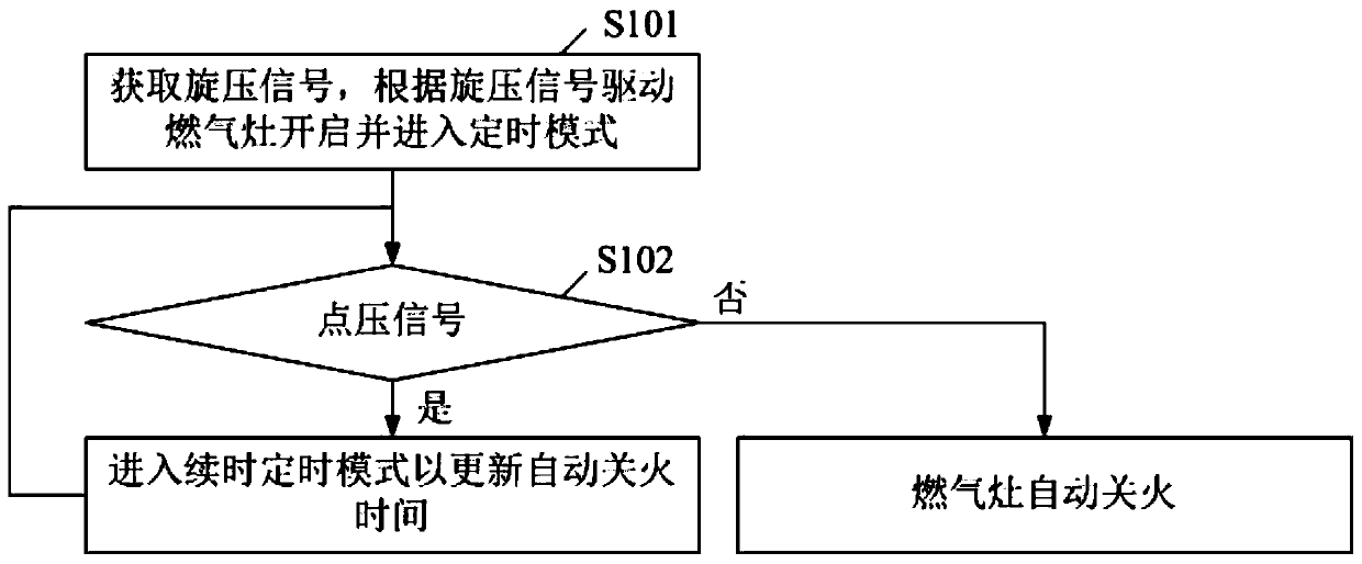
[0048] see figure 1 , figure 1 It shows the flow chart of the first embodiment of the gas stove control method based on the push knob of the present invention, which includes:

[0049] S101. Obtain a spinning signal, and drive the gas stove to turn on and enter a timing mode according to the spinning signal.

[0050] In this embodiment, the timing mode is a point pressing continuous time mode.

[0051] S102. In the point pressure continuation mode, if the controller acquires the point pressure signal, enter the continuation timing mode to update the automatic fire-off time.

[0052] For example, if the preset time of the press-on-time mode is 6 minutes, the automatic fire-off time needs to be updated to 10 minutes. In the state of releasing the electronic child lock, press the knob counterclockwise and cross the self-locking limit position of the cock valve, the gas stove will ignite immediately and start to burn. At this time, the gas stove enters the continuous pressure m...

no. 2 example

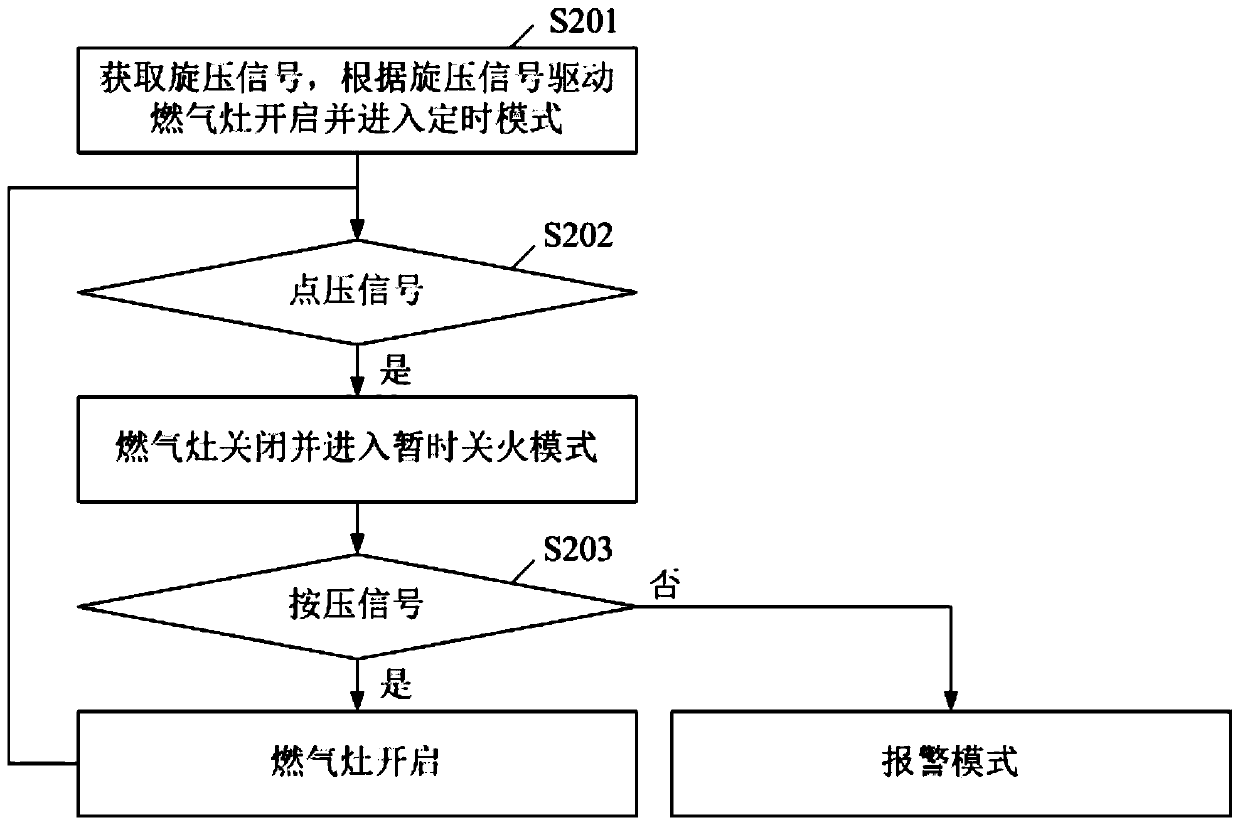
[0055] see figure 2 , figure 2 It shows the flow chart of the second embodiment of the gas stove control method based on the push knob of the present invention, which includes:

[0056] S201. Obtain a spinning signal, and drive the gas stove to turn on and enter a timing mode according to the spinning signal.

[0057] In this embodiment, the timing mode is a pressure-on-fire-off mode.

[0058] S202. In the ignition-off mode with pressure, if a pressure signal is obtained, the gas stove is turned off and enters a temporary ignition-off mode.

[0059] S203. In the temporary fire-off mode, if a pressing signal is obtained, the gas stove is turned on and enters the point-press fire-off mode, otherwise, enters an alarm mode.

[0060] For example, if the preset time of the click-to-fire mode is 6 minutes and the preset time of the temporary fire-off mode is 10 minutes. In the state of releasing the electronic child lock, press the knob counterclockwise and cross the self-locki...

no. 3 example

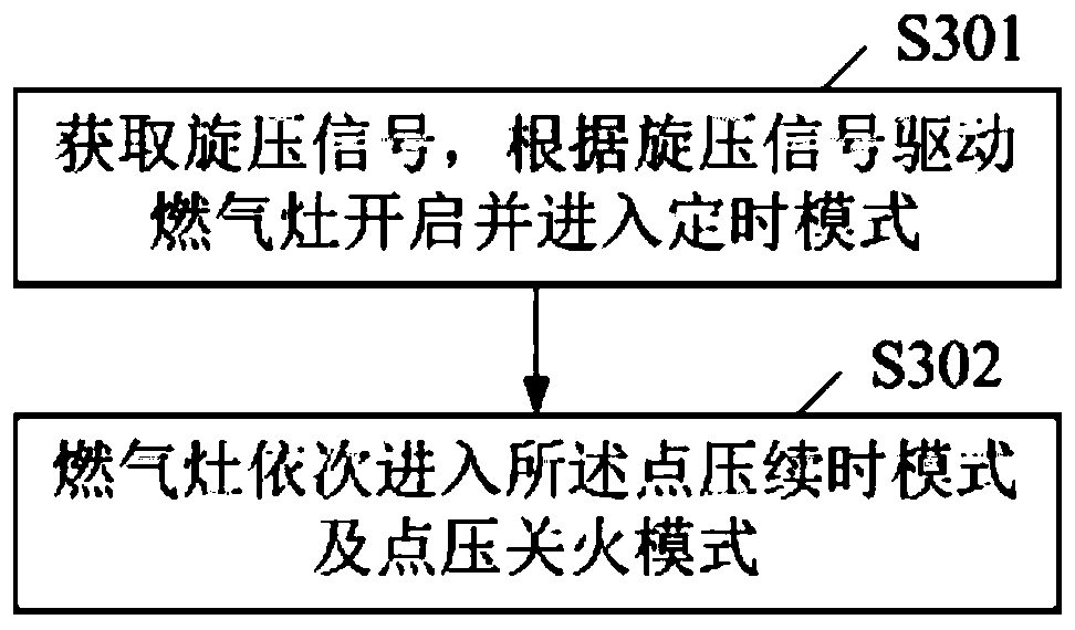
[0063] see image 3 , image 3 It shows the flow chart of the third embodiment of the gas stove control method based on the push knob of the present invention, which includes:

[0064] S301. Obtain a spinning signal, and drive the gas stove to turn on and enter a timing mode according to the spinning signal.

[0065] In this embodiment, the timing mode is a continuous-fire-off mode;

[0066] S302. In the continuation-fire-off mode, the gas cooker sequentially enters the pressure-on-time mode and the pressure-off mode.

[0067] For example, if the preset time of the click-on-time mode is 2 minutes, the preset time of the click-off fire mode is 5 minutes. In the state of releasing the electronic child lock, press the knob counterclockwise and cross the self-locking limit position of the cock valve, the gas stove will ignite immediately and start to burn. At this time, the gas stove enters the continuous pressure mode; Within 2 minutes, if no pressure signal is received, the ...


PUM


Abstract

The invention discloses a gas stove control method based on a pressing type rotary knob. The method comprises the following steps that a spinning signal is obtained, a gas stove is driven to be started and enters a timing mode according to the spinning signal, the timing mode comprises a point-pressing continuous-time mode, a point-pressing turning-off mode, a continuous-time-turning-off mode, a turning-off-continuous-time mode or a constant-time mode; in the point-pressing continuous-time mode, the turning-off time can be automatically updated according to the point-pressing signal; in the point-pressing turning-off mode, the gas stove is driven to be closed or started according to a pressing signal; in the continuous-time-turning-off mode, the gas stove sequentially enters the point-pressing continuous-time mode and the point-pressing turning-off mode, or sequentially enters the point-pressing turning-off mode and the point-pressing continuous-time mode; and in the constant-time mode, the gas stove does not respond to the point-pressing signal. By means of the gas stove control method, most of operation can be realized only by pressing the rotary knob, mechanical abrasion of a cock valve caused by rotating the rotary knob is greatly reduced, the service life of the gas stove is prolonged, the gas leakage amount is reduced, and the safety, convenience, practicability and reliability of the gas stove are improved.

Description

technical field [0001] The invention relates to the technical field of gas stoves, in particular to a method for controlling a gas stove based on a push knob. Background technique [0002] The gas stoves currently sold on the market are divided into single-eye stoves, double-eye stoves, and multi-eye stoves with more than three eyes according to the number of stove holes. Each stove eye is equipped with a corresponding cock valve, and the valve stem of the cock valve A knob is installed on the car, and the consumer operates the knob to realize ignition, turn off the fire, and adjust the size of the firepower. [0003] Specifically, the operation process of the gas stove is as follows: first press down the knob, and then turn the knob counterclockwise to cross the self-locking limit device in the cock valve. Only after turning the knob can the firepower be adjusted. Therefore, if it is necessary to start the fire first, then turn it on, and finally turn off the fire during ...

Claims


Application Information

Patent Timeline
IPC IPC(8): F24C3/12
CPCF24C3/126
Inventor 杨永生
Owner 杨永生
Learn More