Full-automatic turret type solid-phase micro-extraction device

An extraction device and turret-type technology, which is applied in the field of fully automatic turret-type solid-phase microextraction devices, can solve the problems of low efficiency, short detection time requirements, and extraction effects.

Pending Publication Date: 2020-05-08
河南阿尔法科学仪器有限公司
View PDF0 Cites 4 Cited by
  • Summary
  • Abstract
  • Description
  • Claims
  • Application Information

AI Technical Summary

Problems solved by technology

This detection method has high personnel requirements, low efficiency, and large detection error, and is not suitable for modern testing laboratories with large sample volume, high detection accuracy requirements, low personnel operation level, and short detection time requirements.
[0004] And because in actual use, the extraction needle is desorbed in the vaporization chamber after extraction, but there is still residual extract on the extraction needle, and the residual extract will have a greater impact on the next extraction. thus affecting the overall detection accuracy
If there is no special high-temperature aging device for solid-phase microextraction head in the instrument, its aging function is to use the inlet of chromatography and mass spectrometer as the aging port, but when some instruments have only one inlet, the aging temperature cannot be adjusted according to the needs. setting, the aging effect of the solid phase microextraction needle is relatively poor, resulting in a decrease in detection accuracy and a large detection error

Method used


Image

  • Full-automatic turret type solid-phase micro-extraction device
  • Full-automatic turret type solid-phase micro-extraction device
  • Full-automatic turret type solid-phase micro-extraction device

Examples


Embodiment Construction

[0024] The following will clearly and completely describe the technical solutions in the embodiments of the present invention with reference to the accompanying drawings in the embodiments of the present invention. Obviously, the described embodiments are only some, not all, embodiments of the present invention. Based on the embodiments of the present invention, all other embodiments obtained by persons of ordinary skill in the art without making creative efforts belong to the protection scope of the present invention.

[0025] In the description of the present invention, it should be noted that for orientation words, such as the term "center", "horizontal", "longitudinal", "length", "width", "thickness", "upper", "lower" , "Front", "Back", "Left", "Right", "Vertical", "Horizontal", "Top", "Bottom", "Inner", "Outer", "Clockwise", "Counterclockwise" The indicated orientation and positional relationship are based on the orientation or positional relationship shown in the drawing...


PUM


Abstract

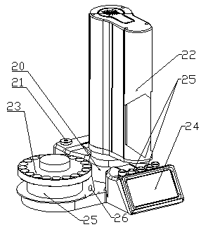
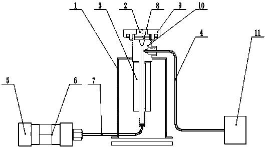
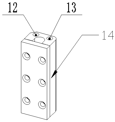
The invention discloses a full-automatic turret type solid-phase micro-extraction device. The full-automatic turret type solid-phase micro-extraction device comprises a turret type automatic sample injector body and a sample injection disc, wherein the turret type automatic sample injector body comprises a turret and a turret base; a display screen is arranged on the side face of the side, adjacent to the sample injection disc, of the turret base. A micro-extraction sample injection module used for being communicated with a chromatographic instrument sample injection port is arranged on the side, opposite to the sample injection disc, of the turret base. An aging device is arranged on the other side, corresponding to the display screen, of the turret base. According to the device, interfaces of sample injection systems such as a chromatographic instrument and the like are arranged on a fixed station of the existing solid-phase micro-extraction instrument; therefore, the turret is automatically controlled; a solid-phase micro-extraction needle is automatically inserted into a sample inlet system of an instrument such as a chromatograph, a station is additionally arranged on a rotating path of a rotating tower of existing equipment, and an aging device is additionally arranged on the station, so that the existing equipment automatically rotates to the station where the aging device is located for aging and nitrogen purging after single-time extraction is finished.

Description

technical field [0001] The invention relates to the technical field of liquid sample injectors, in particular to a fully automatic turret type solid-phase microextraction device. Background technique [0002] At present, solid-phase microextraction (SPME) technology is a commonly used technology for laboratory sample pretreatment. It overcomes the defects of traditional sample pretreatment technology and integrates sampling, extraction, concentration and sample injection. The speed of analysis and detection is greatly accelerated. Solid-phase microextraction technology can be used in the analysis of almost all kinds of volatile or semi-volatile substances in gas, liquid, biological, solid and other samples. It has been developed in the environment, biology, industry, food, It is widely used in various aspects of clinical medicine and other fields. [0003] At present, domestic laboratory micro-extraction devices are all manual. Specifically, the existing solid-phase micro-...

Claims


Application Information

Patent Timeline
Patent Type & Authority Applications(China)
IPC IPC(8): G01N30/06G01N30/08G01N30/24
CPCG01N30/06G01N30/08G01N30/24G01N2030/062
Inventor 王锡栋刘远威路辉丽曹斐梵
Owner 河南阿尔法科学仪器有限公司
Why Eureka
Try Eureka