
An optical fiber connector for high-power laser cable

A fiber optic connector, high-power technology, applied in the coupling of optical waveguide, light guide, optics, etc., can solve the problems of untimely heat transfer, damage to optical devices and equipment, low efficiency, etc., achieve high thermal conductivity and improve optical loss Effect

Active Publication Date: 2020-05-08
YANGZHOU LANDU PLASTICS TECH CO LTD
View PDF11 Cites 0 Cited by
  • Summary
  • Abstract
  • Description
  • Claims
  • Application Information

AI Technical Summary

Problems solved by technology

During direct cooling, the coolant may flow out of the optical connector and seriously damage the optical devices and equipment connected to the connector, and the degree of harm will be far beyond the failure of the optical cable
While indirect cooling has low efficiency and slow heat transfer, there may be localized heat collection, and the heat on the optical fiber may be dissipated into the cooling circuit after permanent damage is caused.

Method used


Image

  • An optical fiber connector for high-power laser cable
  • An optical fiber connector for high-power laser cable
  • An optical fiber connector for high-power laser cable

Examples


Embodiment Construction

[0024] Embodiments of the invention are described in detail below, examples of which are illustrated in the accompanying drawings. The embodiments described below by referring to the figures are exemplary and are intended to explain the present invention and should not be construed as limiting the present invention.

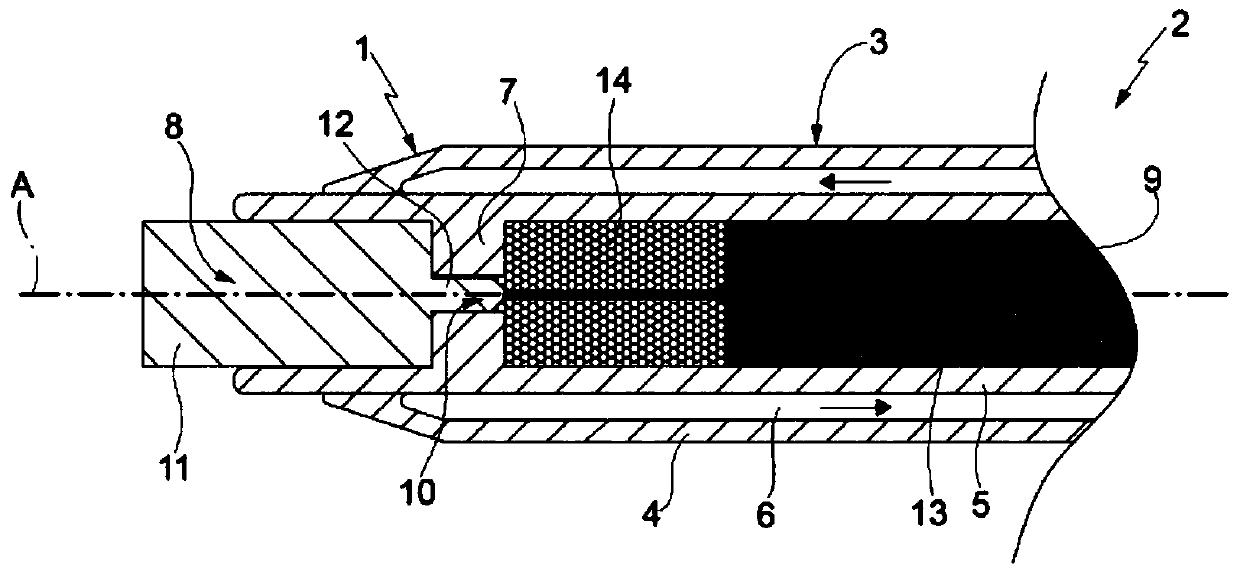
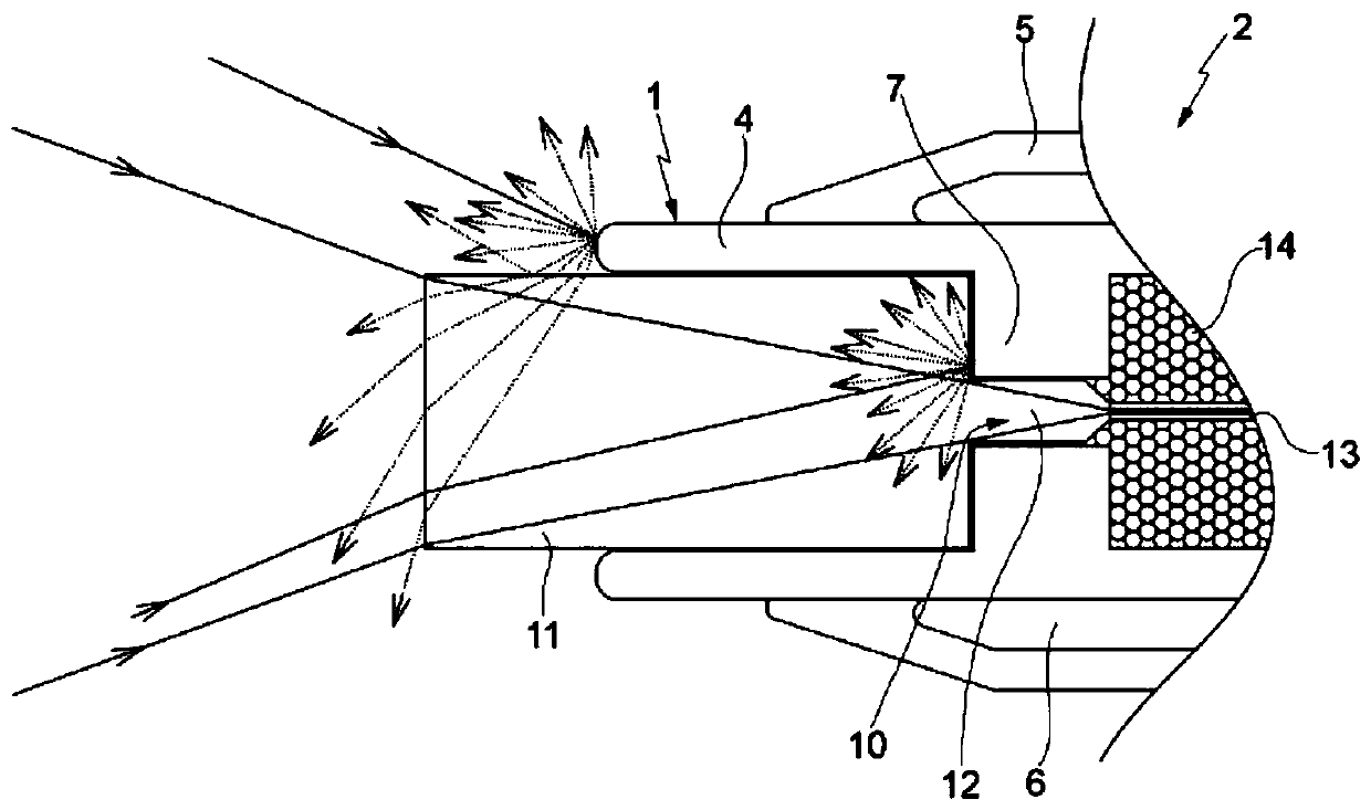
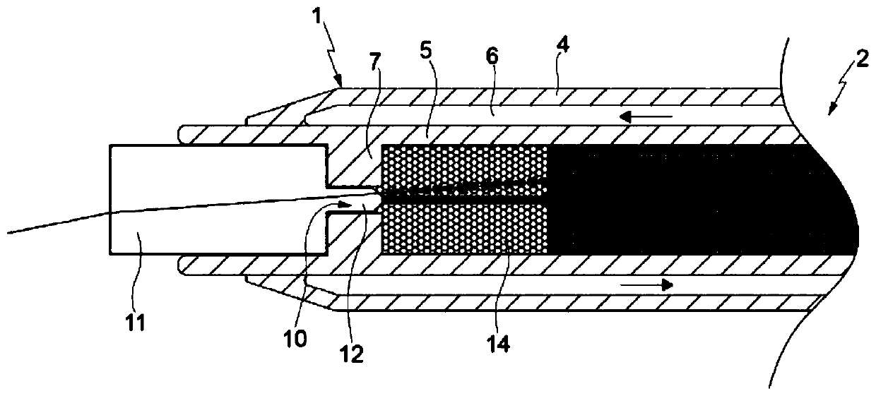
[0025] Such as figure 1 As shown, a fiber optic connector for high-power laser cables of the present invention includes an optical connector body, and the optical connector body includes a sleeve 3; the sleeve 3 includes an inner tube body 5 and an outer tube body 4, The inner tube body 5 is coaxially arranged inside the outer tube body 4, and an annular hollow cavity 6 is formed between the two, which is coaxially arranged with the casing 3 and extends longitudinally. The hollow cavity 6 has an inlet and an outlet to form a cooling cycle , there is a cooling liquid in the hollow cavity 6, according to figure 1 flow in the direction indicated.

[0026] The out...


PUM


Abstract

The invention discloses an optical fiber connector for a high-power laser cable. The optical fiber connector comprises an optical fiber and an optical connector body, wherein the optical connector body comprises sleeves extending along a longitudinal axis A, the sleeves are respectively an inner sleeve body and an outer sleeve body, and an annular hollow cavity coaxial with the longitudinal axis Ais formed between the inner sleeve body and the outer sleeve body; wherein the inner tube body is divided into a first inner cavity and a second inner cavity which are axially spaced, a coupling bodyis arranged in the first inner cavity, the second inner cavity is completely filled with a filling material, the filling material has a light scattering characteristic, and light entering the secondinner cavity through the filling material is scattered and is not coupled with the optical fiber. The optical loss is limited in the optical connector, and proper absorption and dissipation are carried out; an indirect cooling mode is adopted, so that high thermal conductivity among the optical fiber, the coupling area and the wall in contact with the cooling liquid is ensured; lost light and light extracted from the cladding are absorbed and dissipated by fully utilizing the space in the optical connector.

Description

technical field [0001] The invention relates to a fiber optic connector for high power laser cables. Background technique [0002] High-power optical cables can be used as the carrier of laser transmission, and they have been widely used in the industrial field. In actual use, one side of the fiber optic cable is connected to the laser source, and the other side is connected to the corresponding tool or working device. Generally, the optical power coupling of the input and output in the optical fiber occurs at the end of the optical cable. At this time, an optical connector is usually required at the end of the optical cable to simplify the coupling between the optical cable and the tool or working device. However, the optical loss at the coupling point of the optical cable is usually unavoidable, so it must be taken into account. There are many possible reasons for optical loss, such as poor coupling, loss of coupling performance due to inaccurate positioning during use o...

Claims


Application Information

Patent Timeline
Patent Type & Authority Applications(China)
IPC IPC(8): G02B6/38
CPCG02B6/3814G02B6/3845G02B6/3855
Inventor 王庆龙
Owner YANGZHOU LANDU PLASTICS TECH CO LTD
Learn More