Serial multi-channel power distribution switch control circuit

A technology for power distribution switches and control circuits, applied in program control, computer control, general control systems, etc., can solve the problems of complex installation operations, waste of resources, time-consuming and labor-intensive, etc., and achieve the goal of saving pin resources and stabilizing equipment status Effect

Active Publication Date: 2021-02-12
武汉卓目科技有限公司
View PDF9 Cites 0 Cited by
  • Summary
  • Abstract
  • Description
  • Claims
  • Application Information

AI Technical Summary

Problems solved by technology

[0002] At present, the start and stop of electronic and electrical equipment are all controlled by switches. However, when encountering multi-channel switch circuits, due to the single control of the switch series, the installation operation is complicated, time-consuming and labor-intensive, and at the same time the cost is high, which seriously affects the work efficiency of the staff.
[0003] In the face of the disadvantages of multi-way switches, there are also parallel interface circuits on the market to control, but due to the parallel connection, there are many signal pins, resulting in waste of resources
[0004] For the control of multi-way switches, the system has relatively high requirements for synchronous control, and many systems cannot achieve the effect of synchronous switching. Because the system is not powered on synchronously, it will cause startup imbalance equipment failure

Method used


Image

  • Serial multi-channel power distribution switch control circuit
  • Serial multi-channel power distribution switch control circuit
  • Serial multi-channel power distribution switch control circuit

Examples


Embodiment Construction

[0025] In order to make the purpose, technical solutions and advantages of the embodiments of the present invention clearer, the technical solutions in the embodiments of the present invention will be clearly and completely described below in conjunction with the drawings in the embodiments of the present invention. Obviously, the described embodiments It is a part of embodiments of the present invention, but not all embodiments. Based on the embodiments of the present invention, all other embodiments obtained by persons of ordinary skill in the art without making creative efforts belong to the protection scope of the present invention.

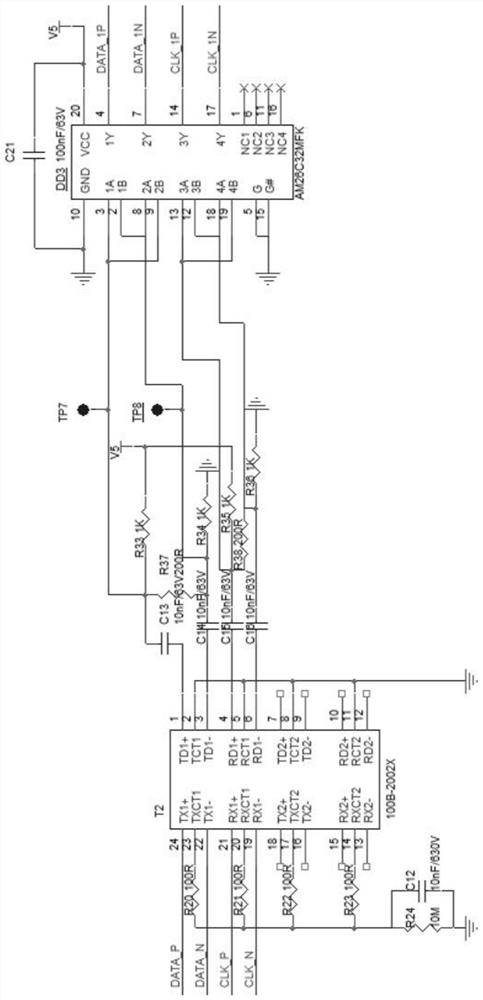
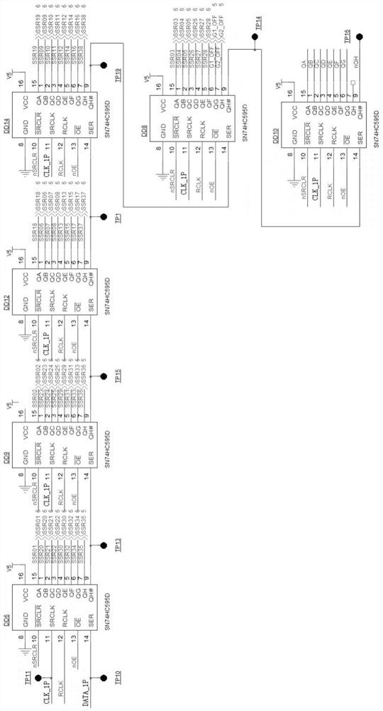
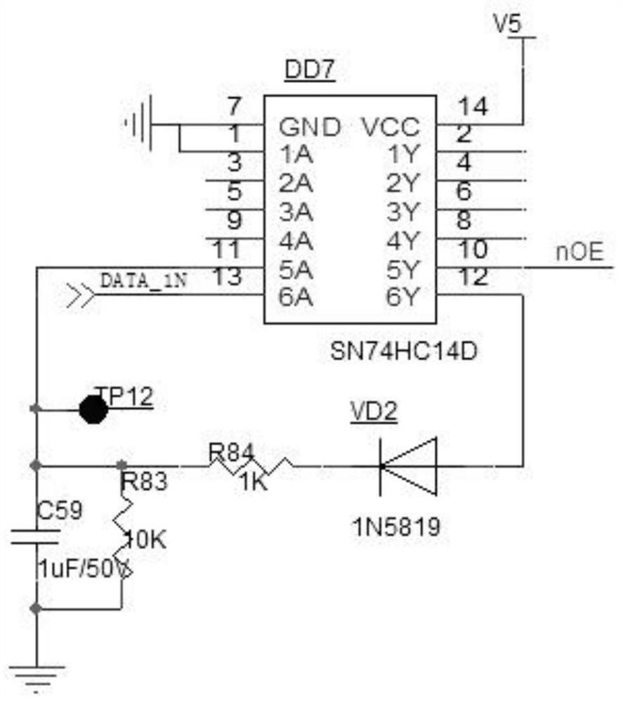
[0026] see Figure 1 to Figure 5 , this embodiment discloses a serial multi-channel power distribution switch control circuit, including a control module, a D flip-flop, an inverter, and a shift register group, and the shift register group includes a plurality of serially connected shift registers, so The signal clock input terminal SRCLK of...


PUM


Abstract

The invention discloses a serial multi-channel power distribution switch control circuit, including FPGA, a shift register group, the serial data input end of the first shift register in the shift register group and the data signal output end of the control module DATA_P connection, the serial data input terminal of other shift registers in the shift register group is connected to the serial data output terminal of the previous shift register adjacent to it, the signal clock input terminal of the shift register is connected to the clock signal of the control module The output terminal CLK_P is connected, the latch clock input terminal of the shift register is connected to the first output terminal of the D flip-flop, the clear signal input terminal of the shift register is connected to the second output terminal of the D flip-flop, and the output of the shift register The enable signal input terminal is connected to the output terminal of the inverter, the input terminal of the inverter is connected to the data signal output terminal DATA_N of the control module, and multiple parallel data output terminals of the shift register are respectively connected to multiple power distribution switches. It saves time and effort, and saves FPGA pin resources.

Description

technical field [0001] The invention relates to the field of electronic and electrical equipment control, in particular to a serial multi-channel power distribution switch control circuit. Background technique [0002] At present, the start and stop of electronic and electrical equipment are all controlled by switches. However, when encountering multiple switch circuits, due to the single control of the switch series, the installation operation is complicated, time-consuming, laborious, and costly, which seriously affects the work efficiency of the staff. [0003] Faced with the disadvantages of multi-way switches, there are also parallel interface circuits on the market for control, but due to the parallel connection, there are many signal pins, resulting in waste of resources. [0004] For the control of multi-way switches, the system has relatively high requirements for synchronous control. Many systems cannot achieve the effect of synchronous switching. Because the syste...

Claims


Application Information

Patent Timeline
Patent Type & Authority Patents(China)
IPC IPC(8): G05B19/042
CPCG05B19/0423G05B2219/25257
Inventor 彭维华李飞杜飞飞周严
Owner 武汉卓目科技有限公司
Why Eureka
Try Eureka