
Fixed-wing unmanned aerial vehicle landing control method based on self-adaptive dynamic inverse

A control method and unmanned aerial vehicle technology, applied in the direction of attitude control, non-electric variable control, control/regulation system, etc., can solve the difficult to meet the complex environment and high precision requirements of unmanned aerial vehicle landing, and the ship deck can be landed Issues such as narrow areas, complex atmospheric disturbances for drone landings, etc.

Active Publication Date: 2020-05-08
NANJING UNIV OF AERONAUTICS & ASTRONAUTICS
View PDF7 Cites 14 Cited by
  • Summary
  • Abstract
  • Description
  • Claims
  • Application Information

AI Technical Summary

Problems solved by technology

[0003] Large-scale fixed-wing UAVs adopt the runway arresting landing method. Unlike land-based landings, UAV landings have the following main difficulties: 1) The landing area on the ship deck is narrow; 2) There are six freedoms on the ship deck. 3) There are complex atmospheric disturbances in the process of UAV landing
In the research of UAV landing control methods, researchers usually use PID-based control methods. The traditional PID design method is difficult to deal with the complex nonlinear coupling and parameter uncertainty of UAVs, and it is difficult to meet the requirements of UAV landing. Due to the complex environment and high precision requirements, it is urgent to propose an advanced control method with high landing accuracy and adaptability to UAV parameter changes.

Method used


Image

  • Fixed-wing unmanned aerial vehicle landing control method based on self-adaptive dynamic inverse
  • Fixed-wing unmanned aerial vehicle landing control method based on self-adaptive dynamic inverse
  • Fixed-wing unmanned aerial vehicle landing control method based on self-adaptive dynamic inverse

Examples


Embodiment Construction

[0094] The technical solutions of the present invention will be described in detail below in conjunction with the accompanying drawings.

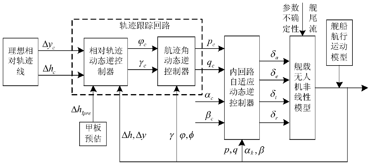
[0095] The present invention designs a fixed-wing unmanned aerial vehicle landing control method based on adaptive dynamic inversion, and the steps are as follows:

[0096] Step 1: Establish a nonlinear model of the UAV under wind disturbance, and obtain the expressions of the force and moment on the UAV;

[0097] Step 2: Design the inner loop control law based on the adaptive dynamic inverse method according to the inner loop differential equation of the UAV;

[0098] Step 3: Design the track angle loop control law based on the nonlinear dynamic inverse method;

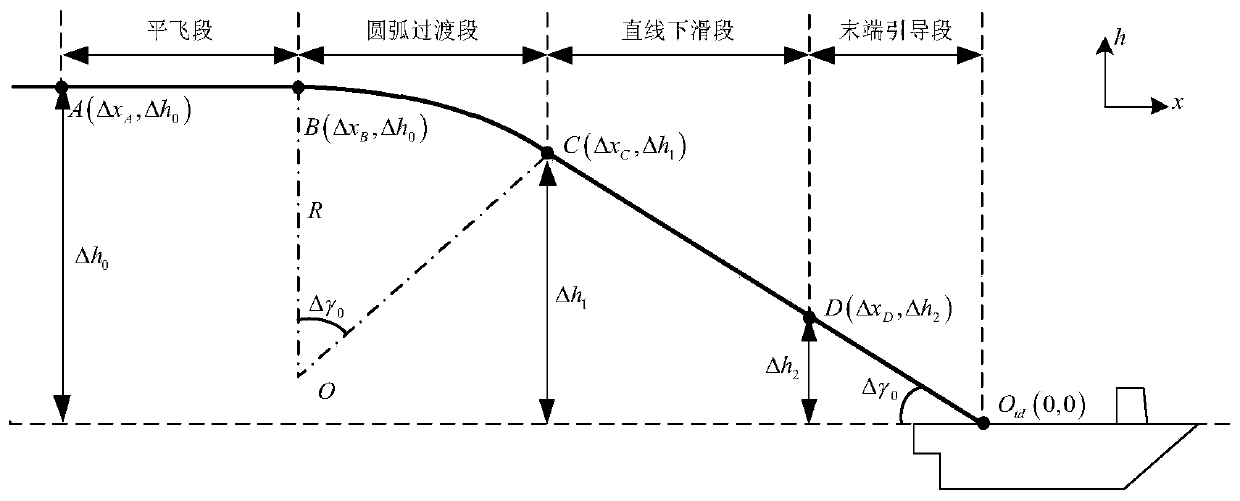
[0099] Step 4: Design the ideal relative trajectory of the UAV landing, the ideal relative trajectory includes the level flight section, the arc transition section, the straight down section and the end guidance section;

[0100] Step 5: Design the relative trajectory loop contr...


PUM


Abstract

The invention discloses a fixed-wing unmanned aerial vehicle landing control method based on self-adaptive dynamic inverse. The method comprises: establishing an unmanned aerial vehicle nonlinear model under wind disturbance; designing an inner loop control law based on an adaptive dynamic inverse method according to an inner loop differential equation of the unmanned aerial vehicle; designing a track angle loop control law based on a nonlinear dynamic inverse method; designing an ideal relative trajectory of unmanned aerial vehicle landing; designing a relative trajectory loop control law based on a nonlinear dynamic inverse method; and correcting the track inclination angle instruction of the tail end guide section according to the estimated value of the ideal landing point. Parameter uncertainty of the unmanned aerial vehicle model can be effectively suppressed, complex nonlinearity and control coupling of the model are overcome, interference of complex wind disturbance such as shipwake flow on the unmanned aerial vehicle track is resisted, deck movement of a ship is rapidly tracked, and the ship landing precision and the ship landing success rate are effectively improved.

Description

technical field [0001] The invention belongs to the field of unmanned aerial vehicle landing control, and in particular relates to a fixed-wing unmanned aerial vehicle landing control method. Background technique [0002] The aircraft carrier is the most important maritime combat weapon, and carrier-based aircraft, as the core force of the aircraft carrier battle group, is of great significance. At present, my country has achieved the successful landing of manned carrier-based aircraft, but there is still a technical gap in the landing of unmanned carrier-based aircraft, and it is urgent to catch up with developed countries in this field. [0003] Large-scale fixed-wing UAVs adopt the runway arresting landing method. Unlike land-based landings, UAV landings have the following main difficulties: 1) The landing area on the ship deck is narrow; 2) There are six freedoms on the ship deck. 3) There are complex atmospheric disturbances in the process of UAV landing. In the resea...

Claims


Application Information

Patent Timeline
IPC IPC(8): G05D1/08G05D1/10
CPCG05D1/0825G05D1/101
Inventor 李春涛彭争聂宏苏子康
Owner NANJING UNIV OF AERONAUTICS & ASTRONAUTICS
Learn More