Cable for hand-held power tool

A hand-held machine tool and cable technology, applied in the direction of coaxial cables, insulated cables, flat/ribbon cables, etc., can solve the problems of difficult construction, easy damage of cables, expensive copper wires, etc., and achieve the effect of improving damage resistance

Pending Publication Date: 2020-05-08
ROBERT BOSCH GMBH
View PDF9 Cites 0 Cited by
  • Summary
  • Abstract
  • Description
  • Claims
  • Application Information

AI Technical Summary

Problems solved by technology

Such cables usually have expensive copper conductors and are very long, making construction difficult
This creates disadvantages during transport and also during work with the hand-held power tool
In addition, the cable is easily damaged

Method used


Image

  • Cable for hand-held power tool
  • Cable for hand-held power tool
  • Cable for hand-held power tool

Examples


Embodiment Construction

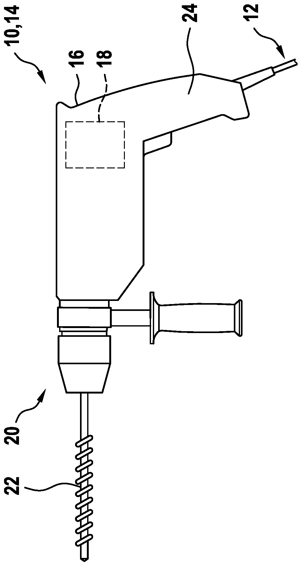
[0022] exist figure 1 A hand-held power tool 10 with a cable 12 according to the invention is shown in a side view. Hand-held power tool 10 is designed, for example, as a drill hammer 14 . Hand-held power tool 14 has a housing 16 in which a drive unit 18 is arranged. The drive unit is coupled to the tool receptacle 20 via a transmission. The tool receptacle 20 is designed for detachably fixing an insertion tool 22 . The drive unit 18 has an electric motor. Housing 16 of hand power tool 10 is designed, for example, in the shape of a pistol. Arranged at the end of the hand-held power tool 10 facing away from the tool receptacle 20 is a handle 24 which extends substantially perpendicularly to the longitudinal extension of the hand-held power tool 10 . The cable 12 is connected to the hand power tool 10 at the lower end of the handle 24 . The cable 12 is electrically connected to the drive unit 18 .

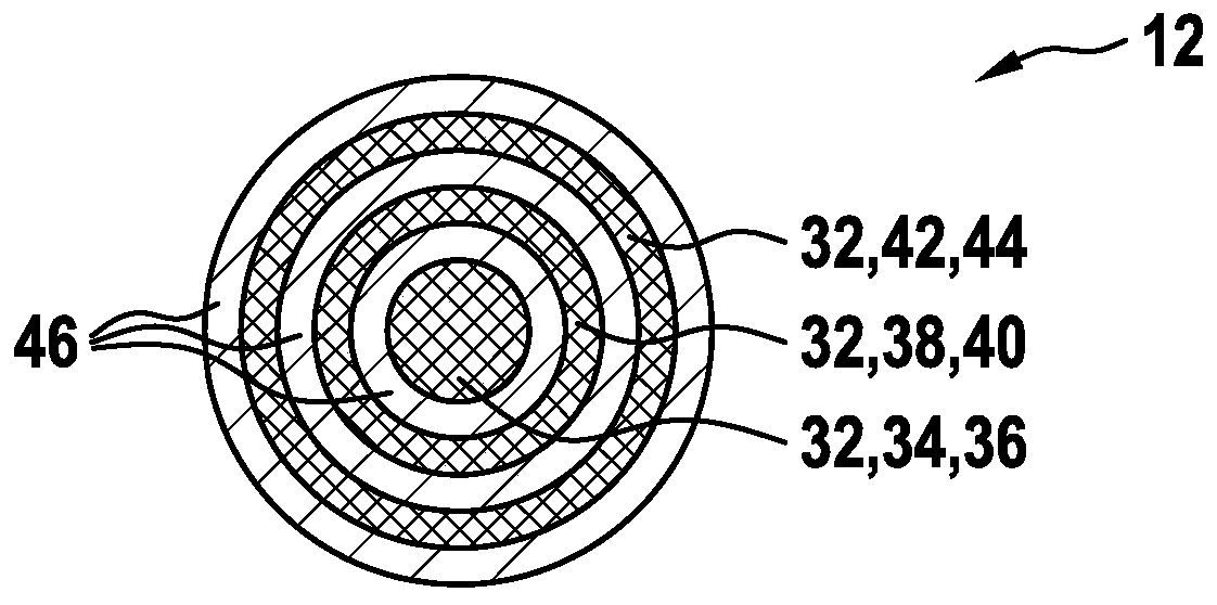
[0023] exist figure 2 A cross-section of the cable 12 is shown in . Th...


PUM


Abstract

The invention relates to a cable for a hand-held power tool, comprising at least one conductor element and at least one insulating element, said insulating element radially surrounding the conductor element. According to the invention, the conductor element is designed as a fiber, a thread, a cord, a belt or other textile forms, which consist essentially entirely of carbon nanotubes or graphene.

Description

technical field [0001] The invention relates to a cable for a hand-held power tool. Background technique [0002] A hand-held power tool is known which can be connected to an energy source via a power cord. Such cables typically have expensive copper conductors and are very long, making construction difficult. This creates disadvantages during transport and also during work with the hand-held power tool. Furthermore, this cable is easily damaged. Contents of the invention [0003] The invention relates to a cable for a hand-held power tool, having at least one conductor element and at least one insulating element, wherein the insulating element radially surrounds the conductor element. The invention proposes that the conductor elements be designed as fibers, threads, threads, ribbons or other formations, in particular textiles, which consist essentially entirely of carbon nanotubes or graphene. As a result, a particularly light and strong cable can advantageously be ac...

Claims


Application Information

Patent Timeline
Patent Type & Authority Applications(China)
IPC IPC(8): H01B7/00H01B7/02H01B7/08H01B7/17H01B1/04H01B5/12
CPCH01B7/0009H01B7/0208H01B7/0861H01B7/17H01B1/04H01B5/12H01B7/183H01B9/04H01B7/0823H01B7/0869
Inventor G·穆奇M·克内
Owner ROBERT BOSCH GMBH
Why Eureka
Try Eureka