Laser cladding wire feeding device

A technology of laser cladding and wire feeding device, applied in the direction of metal material coating process, coating, etc., can solve the problems of increasing the instability of wire feeding, large size of wire feeding mechanism, and failure of wire to pass smoothly, and achieve wire feeding. Stable and reliable, the installation structure is simple and easy to use, and the effect of reducing volume and weight

Inactive Publication Date: 2020-12-11
SHAANXI TIANYUAN MATERIALS PROTECTION TECH
View PDF5 Cites 0 Cited by
  • Summary
  • Abstract
  • Description
  • Claims
  • Application Information

AI Technical Summary

Problems solved by technology

When the wire feeding mechanism conveys the metal wire, different wire diameters require different wire feeding mechanisms, which is poor in versatility; when the powder feeding mechanism conveys the metal wire, it needs to put the metal wire as close as possible to the welding place, and the wire feeding mechanism is bulky and not easy Installed near the laser head, it increases the instability of wire feeding, and the wire is stuck and bent, which will cause the wire to fail to pass smoothly.

Method used


Image

  • Laser cladding wire feeding device
  • Laser cladding wire feeding device
  • Laser cladding wire feeding device

Examples


Embodiment Construction

[0026] The present invention will be further described below in conjunction with the accompanying drawings, so that those skilled in the art can understand the present invention more clearly, but the protection scope of the present invention is not limited thereby.

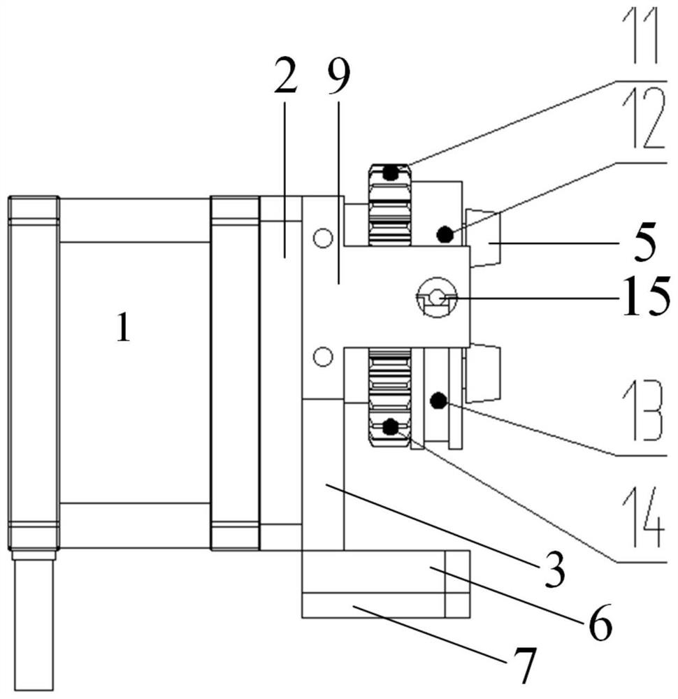
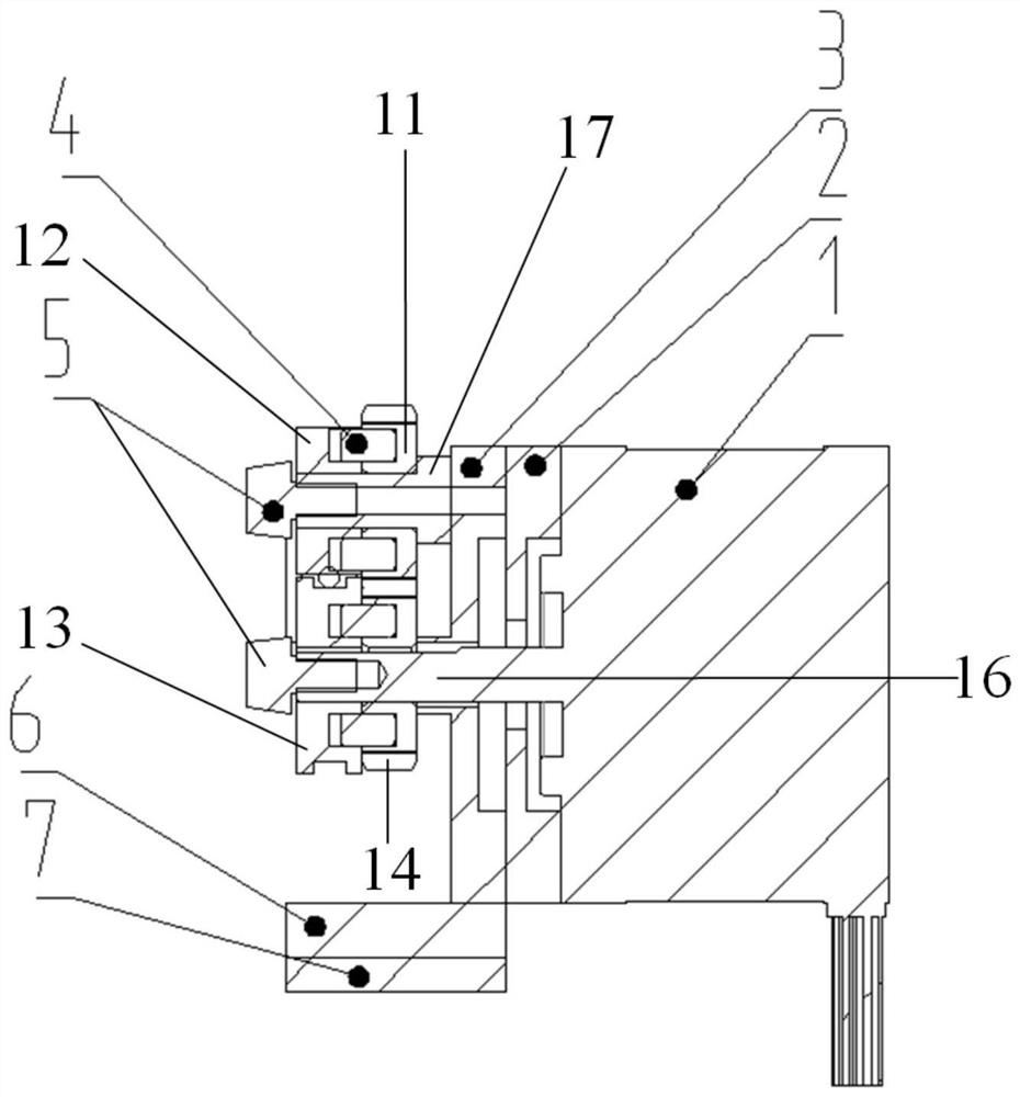
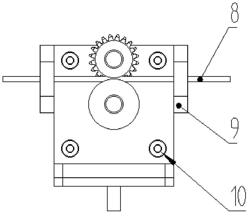
[0027] The present invention proposes a laser cladding wire feeding device, as attached figure 1 As shown, the laser cladding wire feeding device includes: motor 1, first insulating block 2, motor mounting flange 3, positioning pin 4, roller nut 5, flange mounting plate 6, second insulating block 7, wire Material 8, wire material through-hole part 9, insulating sleeve 10, driven wheel 11, wire pressing wheel 12, wire feeding wheel 13, driving wheel 14.

[0028] The motor mounting flange 3 is mounted on the motor 1, and the first insulating block 2 is mounted between the motor 1 and the motor mounting flange 3, and serves as an insulation function between the motor and the flange. The motor 1 and the motor mountin...


PUM


Abstract

The invention provides a laser cladding wire feeding device. The laser cladding wire feeding device comprises a motor, a motor installation flange, a driven wheel, a wire pressing wheel, a wire feeding wheel and a driving wheel, wherein the motor installation flange is installed on the motor; a motor shaft of the motor penetrates through the motor installation flange; a protruding shaft column isarranged on the motor installation flange; the driving wheel and the wire feeding wheel are coaxially installed on the motor shaft side by side and are driven by the motor shaft so as to rotate synchronously; the driven wheel and the wire pressing wheel are coaxially installed on the protruding shaft column side by side and rotate synchronously; the driven wheel and the driving wheel are in meshing transmission connection through a gear; and the driving wheel transmits rotation of the motor shaft to the driven wheel. The device provided by the invention is simple and clear in structure and easy to disassemble and assemble, the addition of the load of other mechanisms does not need to be considered during installation, the installation space of the whole mechanism is saved, the risks of metal wire bending and unsmooth wire feeding can be reduced, the wire feeding stability is improved, the wire replacement time is shortened, the production efficiency is improved, and the development ofthe laser cladding technology is promoted.

Description

technical field [0001] The invention relates to the technical field of laser cladding, in particular to a laser cladding wire feeding device. Background technique [0002] Laser processing is a processing method that uses the characteristics of the interaction between the laser beam and the material to cut, weld, surface treat, drill, and micro-machining the material. It is widely used in laser cladding, laser welding, laser cutting, laser micro-processing, laser Punching and other aspects. Laser cladding is a new type of surface modification technology that uses laser beams to heat the surface of cladding materials and substrates, so that the required special materials are welded to the surface of the workpiece. In the prior art, commonly used cladding materials are metal wires, and the metal wires for cladding are transported to the cladding mechanism through a wire feeding mechanism or a powder feeding mechanism. When the wire feeding mechanism conveys the metal wire, d...

Claims


Application Information

Patent Timeline
Patent Type & Authority Applications(China)
IPC IPC(8): C23C24/10
CPCC23C24/103
Inventor 高原李建勋苏成明
Owner SHAANXI TIANYUAN MATERIALS PROTECTION TECH
Why Eureka
Try Eureka