A fire-resistant cable tray

A cable bridge and bridge technology, applied in electrical components and other directions, can solve the problems of cable fire, affecting the safety of power transmission, unfavorable ventilation and heat dissipation, etc., to achieve the effect of convenient disassembly

Active Publication Date: 2020-11-27
安徽华瑞桥架有限公司
View PDF10 Cites 2 Cited by
  • Summary
  • Abstract
  • Description
  • Claims
  • Application Information

AI Technical Summary

Problems solved by technology

[0002] The cable tray is a device for fixing cables, which can be erected independently or attached to various buildings and pipe gallery supports. It has the characteristics of simple structure, beautiful appearance, flexible configuration and convenient maintenance. The cable tray can be closed or semi-closed Due to the heat generated by the cable itself during operation, the closed design is not conducive to ventilation and heat dissipation. However, in case of fire, the cable bridge with a semi-closed structure cannot play a good role in fire prevention and heat insulation, and it is easy to cause the cable The fire and spread will seriously affect the safety of power transmission. In response to this situation, the existing cable bridge can be sprayed with fire-resistant paint inside. Generally, the thickness is thin, the fire resistance is limited, and the heat dissipation holes are blocked by the expanded and foamed fireproof coating layer, which is difficult to restore, and there are problems in repeated use.

Method used


Image

  • A fire-resistant cable tray
  • A fire-resistant cable tray

Examples


Embodiment Construction

[0030] In order to make the object, technical solution and advantages of the present invention clearer, the present invention will be described in further detail below in conjunction with specific embodiments and with reference to the accompanying drawings.

[0031] It should be noted that all expressions using "first" and "second" in the embodiments of the present invention are to distinguish two entities with the same name but different parameters or parameters that are not the same, see "first" and "second" It is only for the convenience of expression, and should not be construed as a limitation on the embodiments of the present invention, which will not be described one by one in the subsequent embodiments.

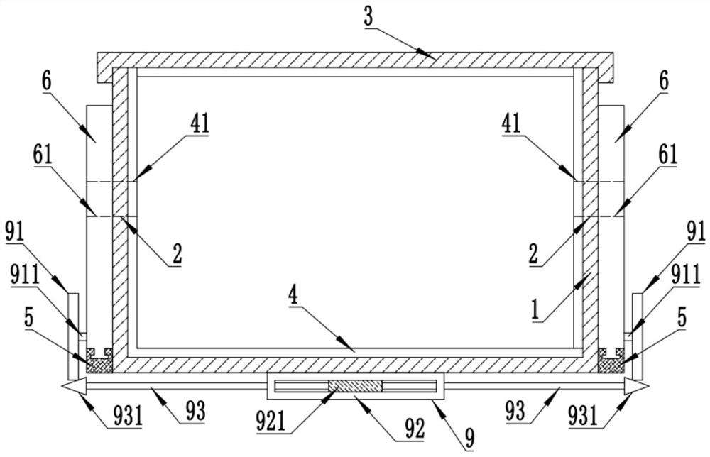
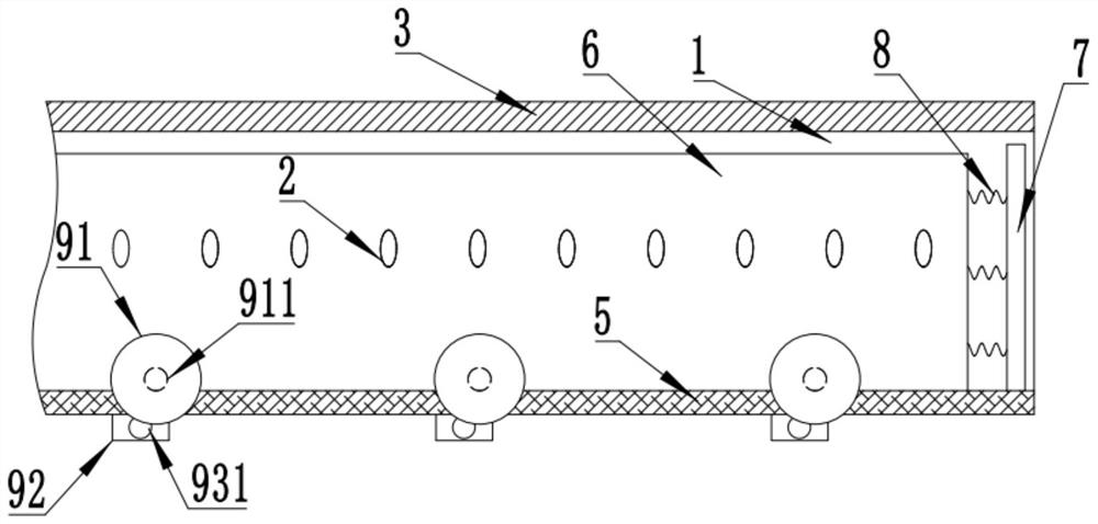
[0032] A fire-resistant cable tray, such as Figure 1 to Figure 2 As shown, it includes a bridge main body 1, a number of cooling holes 2 are provided on the side wall of the bridge main body 1, the upper end of the bridge main body 1 is closed and covered with a cove...


PUM


Abstract

The invention discloses a fire-resistant cable bridge. The fire-resistant cable bridge comprises a bridge main body, a plurality of heat dissipation holes are formed in the side wall of the bridge main body, and a fireproof layer is fixedly attached to the inner wall of the bridge main body. A fireproof sliding plate for fire retardance and thermal insulation is arranged, and the bottom end of thefireproof sliding plate is clamped in the sliding groove. A fire retarding mechanism is arranged, and the fire retarding mechanism comprises a fixed wheel, a temperature sensing cavity and a push rod; a temperature sensing cavity is fixed on the bottom wall of the outer side of the bridge main body; a temperature sensing expansion piece is arranged in the temperature sensing cavity; the temperature sensing expansion piece is heated to expand; the push rod can be pushed, and then the conical side surface of the push rod head can push the fixed wheel so as to drive the fireproof sliding plate to slide and then seal heat dissipation holes, therefore, in case of a fire, high temperature can be automatically sensed to seal the cable bridge, and the fireproof layer in the bridge main body is used for stopping fire and insulating heat; and the fireproof sliding plate can be pulled to slide and reset under the action of the elastic force of the reset spring, so that the cable bridge has ventilation, heat dissipation and fire resistance, and can be automatically reset without influencing repeated use.

Description

technical field [0001] The invention relates to the field of bridge equipment, in particular to a fire-resistant cable bridge. Background technique [0002] The cable tray is a device for fixing cables, which can be erected independently or attached to various buildings and pipe gallery supports. It has the characteristics of simple structure, beautiful appearance, flexible configuration and convenient maintenance. The cable tray can be closed or semi-closed Due to the heat generated by the cable itself during operation, the closed design is not conducive to ventilation and heat dissipation. However, in case of fire, the cable bridge with a semi-closed structure cannot play a good role in fire prevention and heat insulation, and it is easy to cause the cable The fire and spread will seriously affect the safety of power transmission. In response to this situation, the existing cable bridge can be sprayed with fire-resistant paint inside. Generally, the thickness is thin, the...

Claims


Application Information

Patent Timeline
Patent Type & Authority Patents(China)
IPC IPC(8): H02G3/04H02G3/03
CPCH02G3/03H02G3/0406H02G3/0412H02G3/0418H02G3/0437H02G3/0456
Inventor 朱春雷
Owner 安徽华瑞桥架有限公司
Why Eureka
Try Eureka