Eureka AIR delivers breakthrough ideas for toughest innovation challenges, trusted by R&D personnel around the world.

Machining facility for aircraft structural components

A technology for processing equipment and aircraft structures, applied in metal processing equipment, metal processing, aircraft assembly, etc., can solve the problems of long downtime, time-consuming, high cost, etc.

Pending Publication Date: 2020-05-08
布勒特耶自动控制设备有限责任公司
View PDF6 Cites 0 Cited by
  • Summary
  • Abstract
  • Description
  • Claims
  • Application Information

AI Technical Summary

Problems solved by technology

Corresponding work on the top tool is therefore relatively expensive and time-consuming, and thus leads to relatively long downtimes

Method used


Image

  • Machining facility for aircraft structural components
  • Machining facility for aircraft structural components

Examples


Embodiment Construction

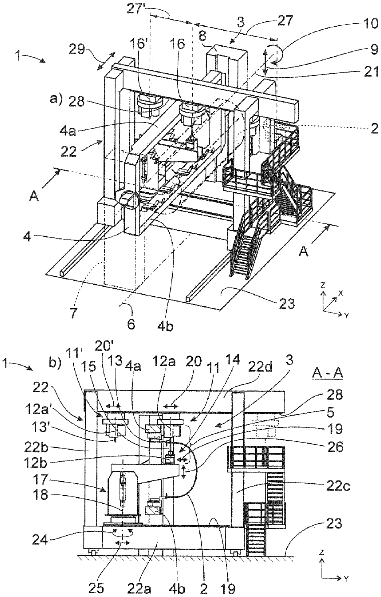
[0022] The shown machining plant 1 is used for machining aircraft structural components 2 which, as mentioned above, can be fuselages, wings or other large aircraft structural components 2 . The processing plant 1 has a processing station 3 . The processing station 3 has, on the one hand, a clamping frame 4 for receiving the corresponding aircraft structural component 2 to be processed and, on the other hand, a processing unit 5 for processing the aircraft structural component 2 .

[0023] The clamping frame 4 extends along a station longitudinal axis 6 which runs in the longitudinal direction X of the processing plant 1 . The extension of the clamping frame 4 along the station longitudinal axis 6 is to be understood broadly. This means that, for example, the clamping frame 4 runs parallel to the station longitudinal axis 6 at least in the initial position when the clamping frame 4 is oriented vertically and / or horizontally.

[0024] The clamping frame 4 is articulated here,...


PUM


Abstract

The invention relates to a machining facility for aircraft structural components (2), comprising a machining station (3) having a mounting frame (4) for receiving each aircraft structural component (2) to be machined, the mounting frame (4) extending along a longitudinal axis (6) of the station, which runs in a longitudinal direction (X), and a machining unit (5) for machining the aircraft structural component (2), comprising a first upper tool unit (11) with an upper tool (13) oriented along a first tool axis (12a) and a lower tool unit (14) with a lower tool (15) oriented along a second toolaxis (12b), the first tool axis (12a) and the second tool axis (12b) being oriented or orientable parallel to a height direction (Z) which is at an angle, particularly orthogonal, to the longitudinaldirection (X), and in at least one machining position of the upper tool (13) of the first upper tool unit (11) and in at least one machining position of the lower tool (15) of the lower tool unit (14), the first tool axis (12a) and the second tool axis (12b) are oriented coaxially to each other. According to the invention, the machining unit (5) comprises a second upper tool unit (11') with an upper tool (13') oriented along a third tool axis (12a'), the third tool axis (12a') being oriented or orientable parallel to the height direction (Z), and in at least one machining position of the upper tool (13') of the second upper tool unit (11') and in at least one machining position of the lower tool (15) of the lower tool unit (14), the second tool axis (12b) and the third tool axis (12a') are oriented coaxially to each other.

Description

technical field [0001] The invention relates to a machining plant for an aircraft structural component according to the preamble of claim 1 and a method for machining an aircraft structural component with a machining plant according to the proposal according to the preamble of claim 12 . Background technique [0002] The manufacture of flying bodies, and in particular aircraft, includes the machining of large aircraft structural components, such as wings and fuselages or parts thereof, in special machining plants. The known machining plant (US 5,778,505 ) on which the invention is based has a machining station with a clamping frame for receiving the corresponding aircraft structural component to be machined. Furthermore, the machining station is equipped with a machining unit in the form of a riveting unit with an upper tool unit having an upper tool and an associated lower tool unit, wherein the lower tool unit has a lower tool, wherein A riveting process can be carried ou...

Claims


Application Information

Patent Timeline
IPC IPC(8): B64F5/10B21J15/14B23Q39/04
CPCB64F5/10B21J13/08B21J15/142B21J15/42B23Q1/623B23Q39/024B23Q1/25B25J5/04B66F11/04
Inventor N.瓦雷尔曼V.内曼
Owner 布勒特耶自动控制设备有限责任公司
Why Eureka
Eureka Blog
Learn More