Automatic quick response temperature measurement for rotary kilns

A temperature measurement and rotary kiln technology, applied in the field of temperature devices, can solve problems such as high risk of injury and health problems, and achieve the effects of increasing work safety, reducing personnel costs, and good process control

Inactive Publication Date: 2020-05-08
OUTOTEC FINDLAND OY
View PDF7 Cites 0 Cited by
  • Summary
  • Abstract
  • Description
  • Claims
  • Application Information

AI Technical Summary

Problems solved by technology

These conditions lead to a high r

Method used


Image

  • Automatic quick response temperature measurement for rotary kilns
  • Automatic quick response temperature measurement for rotary kilns
  • Automatic quick response temperature measurement for rotary kilns

Examples


Embodiment Construction

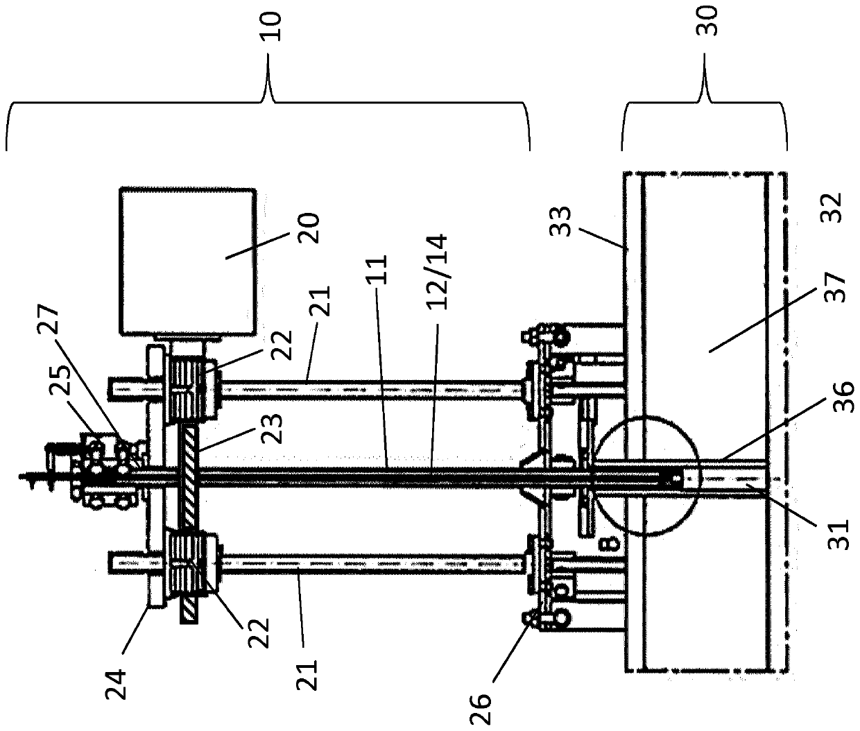
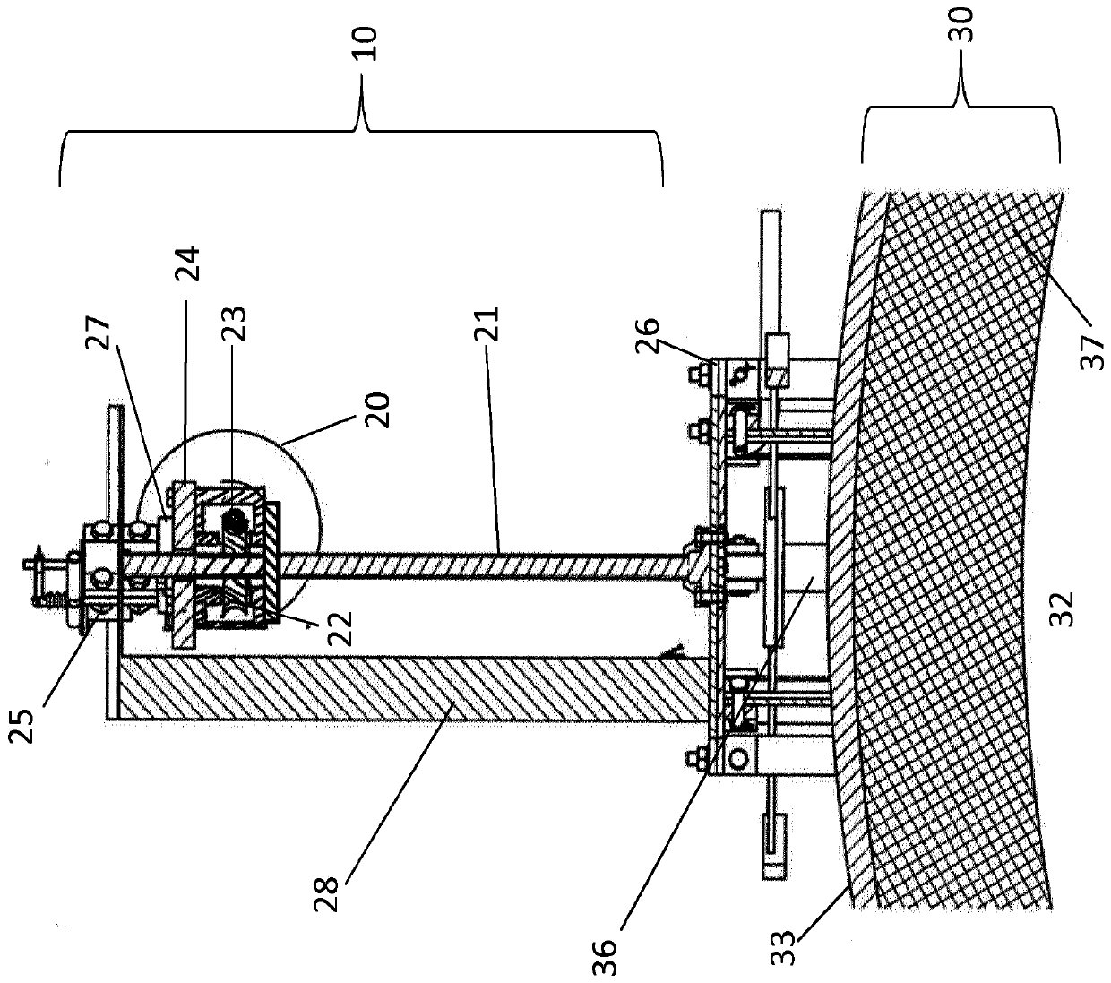
[0057] figure 1 A first semi-automatic embodiment of the invention is shown. Therein, the device 10 is mounted on a rotary kiln housing 33 and performs the working steps for temperature measurement.

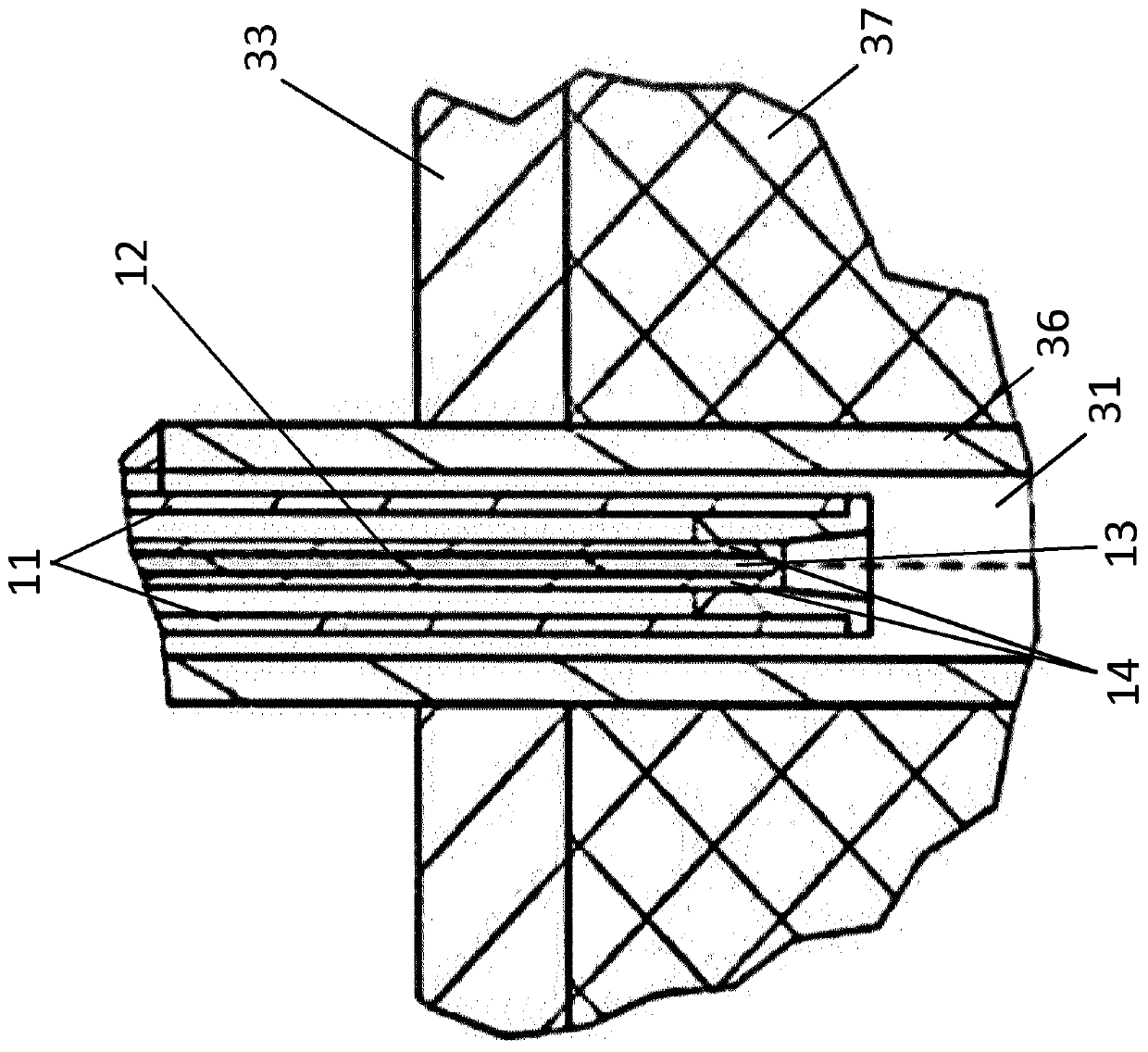
[0058] Specifically, the thermocouple 12 is located in the elongated hollow body 11 . In order to obtain a high response speed, its measuring end 13 is either permanently outside the elongated hollow body 11, or the thermocouple 12 can be moved independently so that its end 13 moves into and out of the elongated hollow body 11 . The thermocouple 12 is preferably protected by a protective tube 14, leaving the measuring tip 13 exposed to allow a rapid response to temperature changes.

[0059] In the latter case, preferably, the tip 13 can be positioned outside the elongated hollow body 11 by means of an actuator 25 on top of the elongated hollow body 11 . The actuator 25 moves the thermocouple 12 together with the protection tube 14 . In the standby position, the elongated ho...


PUM


Abstract

The invention relates to a device (10) for measuring the temperature in a rotary kiln (30) through which solid material passes being heated to elevated temperatures. Said device (10) features a drive(20) as well as an elongated hollow body (11) with means to fix a thermocouple (12), whereby the drive (20) and the elongated hollow body (11) are mounted such that they rotate jointly with the rotarykiln (30). The drive (20) can move the elongated hollow body (11) together with thermocouple (12) through an opening (31) in and out of the rotary kiln interior (32) for measuring the temperature inside the rotary kiln (30) during operation.

Description

technical field [0001] The invention relates to a device for measuring the temperature in a rotary kiln through which material is heated to an elevated temperature. The invention also relates to a rotary kiln equipped with said device and a process for measuring the internal temperature of said rotary kiln on site. Background technique [0002] Temperature measurement is especially important for every process control. Especially for continuous processes, these measurements must be with position and time resolution. Such measurements are particularly challenging for a rotary kiln, a pyrometallurgical processing unit used to thermally treat solid materials (calcination or direct reduction) at high to very high temperatures in a continuous process. [0003] Typically, thermocouples (mainly thermoelectric pyrometers) fastened to the kiln shell and rotating with the kiln have been used. As disclosed, for example, in DE 1 473 305, radiation pyrometers are fastened to the kiln s...

Claims


Application Information

Patent Timeline
IPC IPC(8): F27B7/42G01K1/14F27D19/00F27D21/00
CPCF27B7/42F27D19/00F27D21/0014G01K1/146F27D2019/0018G01K13/08F27D2019/0059G01K7/02
Inventor N·厄特尔E·施密特A·舒拉寇-克拉斯L·福马内克
Owner OUTOTEC FINDLAND OY
Why Eureka
Try Eureka