Method for improving precision of dust detection sensor

A dust detection and sensor technology, applied in the field of sensors, can solve problems such as the reduction of dust sensor accuracy, and achieve the effect of improving measurement accuracy and measurement stability

Active Publication Date: 2020-05-12
TIANKE INTELLIGENT TECH CO LTD
5 Cites 8 Cited by

AI-Extracted Technical Summary

Problems solved by technology

[0008] The invention provides a method for improving the precision of dust detection sensors, whic...

Method used

(1) the dust detection device is arranged on the mode outside the transfer pipe connecting the dust bucket of the vacuum cleaner and the air duct pipe, and the detection of the dust signal is carried out from the position near the entrance of the dust suction vacuum cleaner, realizing accurate collection of current dust concentration, The effect of identifying large particles of dust, and through the protection of the transparent window, reduces the dust backlog at the transmitter and receiver of the dust detection device, avoids the sensitivity drop during the use of the dust sensor, and improves the accuracy of dust concentration detection.
Because the air pressure detection value of different positions can be obtained by air pressure sampling trachea sampling, and multiple reliable and cheap air pressure detection chips have been provided under the prior art, therefore, a plurality of detection positions can be set for a vacuum cleaner, and according to Different critical values ​​are specifically set for different detection positions to achieve different control effects.
Carry out manual speed regulation to vacuum cleaner through described induction button 411, and described independent button 412 can control vacuum cleaner to enter automatic speed regulation, has obtained the technical effect of the combination of vacuum cleaner automatic speed regulation and manual speed regulation, has effectively improved User's operating experience.
The embodiment of the present application provides a method for improving the accuracy of the dust detection sensor, solves the problem that the dust detection sensor in the prior art cannot automatically calibrate the sensor sensitivity when detecting the dust concentration, and uses the mode of the emission intensity of the automatic dust detector Calibration of dust detection sensor sensitivity is realized.
[0088] The vacuum cleaner display device 110 provided in the embodiment of the present application adopts light emitter assemblies arranged in a set order, and provides the first display instruction corresponding to the set measurement parameters through the controller, so that the drive unit drives to emit light The device emits light according to the requirements, and realizes the effect of displaying the actually measured parameter information of the vacuum cleaner according to the light-emitting state of the light-emitting device assembly. Due to the control of the first display command, the number of display states of the light-emitting device assembly is expanded, and then expanded. The display range of the parameter information of the vacuum cleaner is widened. When it is applied to the display of dust concentration, different dust concentrations can be displayed, which is used to remind the user to perform subsequent operation control on the vacuum cleaner according to the current dust concentration information.
[0102] In another embodiment of the present invention, the display device 110 includes a drive unit 112 and a display screen 115, and the display screen 115 is an integrally designed display, which simultaneously displays power information, battery power information, communication information, One or more of fault information or dust concentration information, the drive unit 112 is used to drive the display to display the corresponding information. In this embodiment, the display screen 115 is a liquid crys...

Abstract

The invention relates to the field of sensors, in particular to a method for improving the precision of a dust detection sensor. The method comprises the following steps: providing an electric drive VT with a determined numerical value for an emitter of the dust detection sensor in a calibration working environment; receiving a detection electric signal VR output by a receiver of the dust detection sensor; comparing the numerical value of the detection electric signal VR with the numerical value of a preset reference signal VS, and judging whether the difference value of the two numerical values is within a preset range or not. Compared with the prior art, the sensitivity of the dust detection sensor is calibrated in real time in the dust concentration detection process, the dust sensor isprevented from working at an improper measurement curve position, and therefore the measurement precision and the measurement stability of the dust detection sensor are effectively improved.

Application Domain

Electric equipment installation

Technology Topic

Electric driveAtmospheric sciences +6

Image

  • Method for improving precision of dust detection sensor
  • Method for improving precision of dust detection sensor
  • Method for improving precision of dust detection sensor

Examples

  • Experimental program(1)

Example Embodiment

[0047] In the following description, many specific details are explained in order to fully understand this application. However, this application can be implemented in many other ways different from those described herein, and those skilled in the art can make similar promotion without violating the connotation of this application. Therefore, this application is not limited by the specific implementation disclosed below.
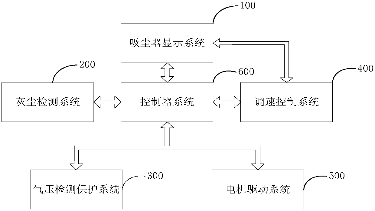
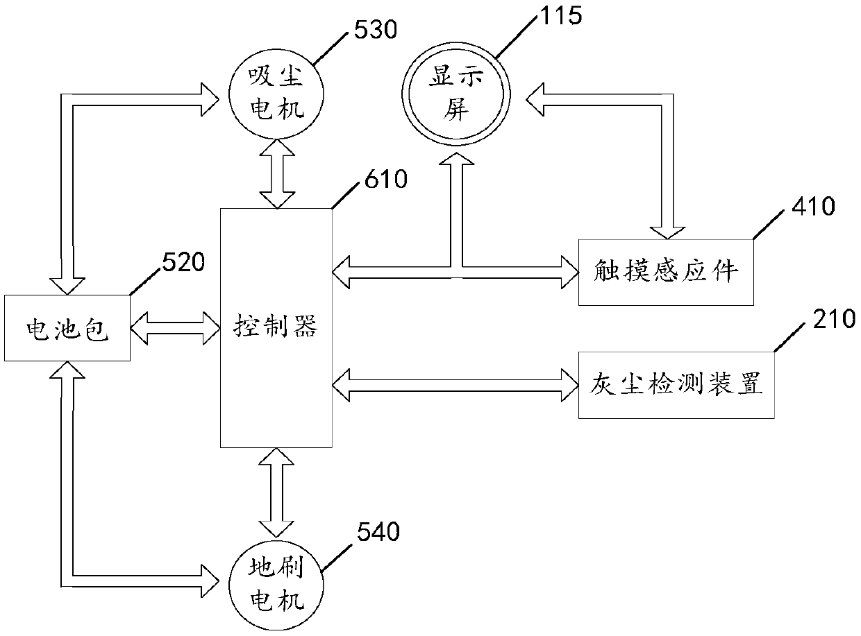
[0048] Please refer to figure 1 with figure 2 , figure 1 It is the logical block diagram between the various systems of the vacuum cleaner of this application; figure 2 This is the logical block diagram of the internal modules of the vacuum cleaner of this application;
[0049] The present application provides a handheld vacuum cleaner, which includes a vacuum cleaner display system 100, a dust detection system 200, an air pressure detection and protection system 300, a speed control system 400, a motor drive system 500, and a control system 600. Among the above-mentioned various systems, the control system 600 has a control and information feedback relationship with other various systems. Therefore, there may be some overlapping and combined parts between the other various systems and the control system.
[0050] The vacuum cleaner display system 100 includes: parts related to display control in the controller of the control system 600, and a vacuum cleaner display device 110; the vacuum cleaner display device 110 includes a light-emitting display unit 111, a drive unit 112, a battery power display unit 113, and a power display unit 114 and display 115;
[0051] The dust detection system 200 includes: parts related to dust detection control in the controller of the control system 600, and a dust detection device 210; the dust detection device 210 includes: a sensor 211, a transparent window 212, a sensor circuit 213, a motor module 214, and a suspension Bar 215 and hanging bar baffle 216.
[0052] The control system 600 includes: a controller 610 and a converter 620. The controller 610 can be implemented by using an MCU control chip plus related peripheral circuits. The printed circuit board on which the MCU control chip is located can be called the main control board. Sometimes the symbols of the control chip are used directly in the drawings to show that it does not affect Note that in the description of this embodiment, the controller 610 is all used to refer to the aforementioned slightly different concepts.
[0053] The air pressure detection and protection system 300 includes: an air pressure detection module 310, a comparator 320, a first controller 611 in the controller 610 that controls air pressure, and a first converter 621 in the converter 620 that controls air pressure.
[0054] The speed control system 400 includes: a touch sensor 410, a power control device 420, a touch panel 430, a second controller 612 in the controller 610 that controls power, and a second converter 622 in the converter that controls power;
[0055] The motor drive system 500 includes: a power switch button 510, a battery pack 520, a dust collection motor 530, and a floor brush motor 540.
[0056] The controller 610 is provided with a trigger circuit. After the user turns on the power switch button, the trigger circuit activates the battery signal, and the battery pack 520 is activated.
[0057] The controller 610 has a data interface with the vacuum cleaner display device 110, the battery pack 520, the vacuum motor 530, the floor brush motor 540, and the power control device 420, and communicates through the data interface.
[0058] The battery pack 520 provides power for the dust collection motor 530, the floor brush motor 540, and the power control device 420. There is an interface protocol between the battery pack 520 and the controller 610, and the interface protocol adopts an open protocol, which is sufficient to communicate with the controller 610 The interior of the battery pack 520 can be freely designed. The battery pack 520 can use battery packs of different manufacturers or different types of battery packs, and change the shape of the battery pack according to different shapes of vacuum cleaners; after the controller 610 obtains the power information of the battery pack, After corresponding processing, the battery power information is transmitted to the vacuum cleaner display device 110, and is displayed by the battery power display portion 113 of the vacuum cleaner display device 110.
[0059] The power control device 420 is connected with the controller 610 through a data interface. After the controller 610 obtains the power information of the vacuum cleaner, it transmits the motor power information of the vacuum cleaner motor 530 to the vacuum cleaner display device 110, and then through the power display unit 114 of the vacuum cleaner display device 110 To display. The interface protocol also adopts an open protocol, and it is sufficient to communicate with the controller 610. Unless otherwise specified, the interface protocols appearing below have the same meaning.
[0060] The following describes the vacuum cleaner display system 100 of the present application. As mentioned above, the vacuum cleaner display system 100 includes a portion of the vacuum cleaner controller related to display control and a display device 110. The following mainly introduces the display device 110.
[0061] Please refer to image 3 , Figure 4 ,with Figure 5 , image 3 It is the logical block diagram of the display device of the vacuum cleaner of this application; Figure 4 It is a schematic diagram of the display device of the vacuum cleaner when displaying information; Figure 5 Yes Figure 4 Enlarged view of center B.
[0062] The vacuum cleaner display device provided by this application is applied to a vacuum cleaner to display parameter information of the vacuum cleaner when it is working. The parameter information of the vacuum cleaner may be power information, battery power information, communication information, fault information or dust concentration information. One or more. The vacuum cleaner display device is generally arranged on a surface that is easy to observe when the vacuum cleaner is working, such as an upward surface, so that the user can know the change of parameter information at any time when using the vacuum cleaner, so as to make an effective judgment on the usage state of the vacuum cleaner. According to the shape of the vacuum cleaner, the appearance of the vacuum cleaner display device can be set to a corresponding shape, such as a circle, a rectangle, or a heart shape, and there is no restriction on this.
[0063] In this embodiment, the vacuum cleaner display device 110 includes at least: a light-emitting display unit 111 and a driving unit 112; and may also include a display screen 115 on which a battery power display unit 113, a power display unit 114, and a communication Display unit (not shown) and fault display unit (not shown). The light-emitting display unit 111 can be installed separately or integrated with the display screen 115. In some preferred embodiments, the light-emitting display unit 111 and the display screen 115 are integratedly designed display devices, and the display device can be selected Any display device such as LED lamp, LCD, OLED, and display with touch function. Of course, according to the specific requirements of different models of vacuum cleaners, according to the parameter information that needs to be displayed, you can choose the light-emitting display unit 111, the battery power display unit 113, the communication display unit (not shown) and the fault display unit (not shown) or power One or more of the display parts 114 omit other parts of the components.
[0064] In this embodiment, the communication display part is used to display the communication status of the display device, and different communication statuses are displayed with different patterns; this communication can be a wired communication method or a wireless communication method; specifically, it can be a display The communication between the device and the vacuum cleaner may also be the communication between the display device and the smart terminal. The fault display part is used to display the fault information of the vacuum cleaner. This fault information can be any kind of fault information that appears during the operation of the vacuum cleaner, including the fault information such as the blocking of the roller brush, the clogging of the dust suction pipe, and the fault of the dust sensor. The fault information can be displayed with different characters and/or patterns.
[0065] Wherein, the light-emitting display unit 111 is used to display the dust concentration information of the vacuum cleaner; the driving unit 112 is used to receive the first display instruction corresponding to the set measurement parameter measurement value from the controller 610, and give the light-emitting display unit 111 provides a driving signal to make the light-emitting display unit 111 present different light-emitting states according to the specific value of the first display instruction, so as to display the dust concentration information.
[0066] The battery power display unit 113 is used to display battery power information of the current state of the vacuum cleaner; the power display unit 114 is used to display power information of the current vacuum cleaner motor 530 of the vacuum cleaner. The display screen 115 and the controller 610 have an interface protocol. After the interface protocol is defined, displays of different models, manufacturers, or shapes can be applied to the vacuum cleaner display device 110 in the embodiment of the present application.
[0067] The light-emitting display unit 111 is composed of a plurality of light-emitting devices arranged in a set order, and is arranged on the surface of the vacuum cleaner. Since the display content of the light-emitting display unit 111 is relatively conspicuous, it is generally used to display the dust concentration information that is most concerned, of course, it is not ruled out. To display other information.
[0068] Wherein, the light emitting device may be a plurality of LEDs (abbreviation of light emitting diode, namely light emitting diode) lamps, and the arrangement of the light emitting devices in a set order means that the light emitting devices are arranged in a certain shape and order. It can be one of geometric shape distribution, character arrangement or pattern. A typical geometric shape distribution arrangement is that a plurality of LEDs are arranged in a circular ring.
[0069] In the embodiment of the present application, the light-emitting device is an LED, etc., and the setting sequence of the light-emitting device is an annular arrangement as an example for description. The LED lamp may include two colors arranged alternately or side by side. For example, the LED lights are red and blue two-color lights; in this embodiment, the LED lights are used to display the dust concentration information of the vacuum cleaner. At any time when the vacuum cleaner is working, each LED light displays one color, and all LED lights Corresponding to the detection result of the dust state, as the working time of the vacuum cleaner increases, the amount of dust changes, and the light-emitting display unit 111 displays the change in dust concentration, thus reminding the user to perform corresponding actions in different states according to the displayed effect when using the vacuum cleaner operating.
[0070] The light emitting device can emit light when the driving unit 112 provides electric driving (current or voltage). The light-emitting display unit 111 provides corresponding display information to the outside through one or more factors of the light-emitting quantity, light-emitting position, and light-emitting mode of the light-emitting device; in this embodiment, it is to provide dust concentration information.
[0071] The driving unit 112 receives the first display instruction corresponding to the measurement value of the set measurement parameter provided by the controller 610, and generates a corresponding electric drive signal according to the specific value of the first display instruction, that is, appropriate The corresponding light-emitting device of the light-emitting display unit 111 is driven to emit light as required. That is, the controller 610 forms a corresponding first display instruction according to the dust concentration detection value provided by the dust detection system 200, and the driving unit 112 generates a suitable display instruction according to the value of the first display instruction. The current or voltage can drive the appropriate number, color and position of light-emitting devices to emit light, so as to provide users with detection information of dust concentration. In this embodiment, the light-emitting display unit 111 includes two-color light-emitting devices as an example, where the more light-emitting devices of the first color are lit, the lower the dust concentration; the more light-emitting devices of the second color are lit , Indicating the higher the dust concentration.
[0072] It is assumed that the light emitting devices of the light emitting display unit adopt circularly arranged LED lights, and have two colors, such as red and green, and the LED lights of the two colors are arranged alternately or side by side. In the case of using the above-mentioned form of light-emitting display unit, the following describes the specific display method of using this light-emitting display unit to display the dust concentration; please also refer to Figure 4.
[0073] When the dust concentration is less than or equal to the minimum threshold, the light-emitting devices of the first color are all on, and the light-emitting devices of the second color are all off, see the situation shown in A1; the minimum threshold is a set for the vacuum cleaner according to the working environment of the vacuum cleaner Threshold, this value reflects the situation that the dust concentration is very low; if the dust concentration is lower than this threshold, the vacuum cleaner is working in a very clean state, and the vacuum motor can run at the lowest power or speed.
[0074] When the dust concentration is greater than or equal to the highest threshold, the light-emitting devices of the first color are all off, and the light-emitting devices of the second color are all lit, see the situation shown in A2; the highest threshold is a set for the vacuum cleaner according to the working environment of the vacuum cleaner Threshold, this value reflects the situation that the dust concentration is very high; if the dust concentration is higher than this threshold, the vacuum cleaner is working in a very dusty state, and the dust suction motor should run at the maximum power or maximum speed. At this time, the light emitting devices of the second color are all lit, which can prompt the user to take measures.
[0075] When the dust concentration is between the lowest threshold and the highest threshold, the light-emitting device is lit in the following manner: starting from the starting point set by the circle, according to the specific value, the second-color light-emitting device of the corresponding radian is lit in proportion ; The remaining radian range lights up the light-emitting device of the first color, see the situation shown in A3.
[0076] In another optional embodiment, the LED lamp of the light-emitting device uses a monochromatic lamp to display the dust concentration, specifically:
[0077] When the dust concentration is less than or equal to the minimum threshold, the light-emitting devices of the first color are all extinguished, see the situation shown in A1;
[0078] When the dust concentration is between the lowest threshold and the highest threshold, according to the specific value of the first display command, the number of light-emitting devices in the first color will light up, and the dust concentration will be displayed in an arc-shaped light strip, see the situation shown in A3 ; The arc range of the arc-shaped light strip represents the size of the dust concentration.
[0079] When the dust concentration is greater than or equal to the highest threshold, the light-emitting devices of the first color are all lit, and the dust concentration is displayed in a ring-shaped light strip, see the situation shown in A2.
[0080] In yet another optional implementation manner, the LED lamp displays the dust concentration in a two-color lamp mode, specifically:
[0081] When the dust concentration is less than or equal to the minimum threshold, the light-emitting devices of the first color are all on, and the light-emitting devices of the second color are all off, see the situation shown in A1;
[0082] When the dust concentration is greater than or equal to the highest threshold, the light-emitting devices of the first color are all extinguished, and the light-emitting devices of the second color are all lit, see the situation shown in A2;
[0083] When the dust concentration is between the lowest threshold and the highest threshold, the light-emitting device is lit in the following manner: starting from the starting point set by the circle, according to the specific value, the second-color light-emitting device of the corresponding radian is lit in proportion ; The remaining radian range lights up the light-emitting device of the first color, and the light-emitting device of the first color and the light-emitting device of the second color cross a certain number of light-emitting devices for overlapping display, showing the effect of color gradation, see the situation shown in A4.
[0084] In yet another alternative embodiment, the LED lamp displays the dust concentration in a two-color lamp mode, specifically:
[0085] When the dust concentration is less than or equal to the set threshold, all the light-emitting devices of the first color are lit or the light-emitting devices of the first color are displayed in a breathing state (ie flashing display), and the light-emitting devices of the second color are all turned off;
[0086] When the dust concentration is greater than or equal to the set threshold, all the light-emitting devices of the second color are lighted up or the light-emitting devices of the second color are displayed in a breathing state (that is, flashing display), and the light-emitting devices of the first color are all off.
[0087] The working status of the vacuum cleaner display device in the embodiment of the application is that the user presses the power switch button, activates the trigger circuit, gives a start battery signal, and the floor brush motor works according to a preset gear position, and the drive unit 112 provides current or The voltage-driven light-emitting display unit 111 emits light, and the light-emitting state of the light-emitting display unit 111 when the power is turned on displays the current dust concentration; as the inhaled dust concentration changes, the controller receives the changed dust concentration information and performs corresponding After processing, the driving unit 112 is caused to receive the first display instruction, and perform corresponding light emission according to any of the above-mentioned light-emitting modes, and the light-emitting display unit 111 at this time displays the changed dust density corresponding to the light-emitting state.
[0088] The vacuum cleaner display device 110 provided by the embodiment of the present application adopts light-emitting device components arranged in a set order, and provides a first display instruction corresponding to the set measurement parameter through the controller, so that the driving unit drives the light-emitting device according to requirements Luminescence realizes the effect of displaying the actually measured parameter information of the vacuum cleaner according to the light-emitting state of the light-emitting device assembly. Due to the control of the first display instruction, the number of display states of the light-emitting device assembly is enlarged, and the number of the vacuum cleaner is enlarged. The display range of parameter information, when applied to the display of dust concentration, can display different dust concentrations to remind the user to perform subsequent operation control of the vacuum cleaner according to the current dust concentration information.
[0089] In addition to the light-emitting display unit 111, the display device 110 may also include a display screen 115. In this embodiment, the display screen 115 is arranged at the center of the LED lights arranged in a circular ring; Related display items can be set on the screen 115 as required. In this embodiment, the display screen 115 is provided with a battery power display unit 113, a power display unit 115, a communication display unit (not shown), and a fault display unit ( Not shown). In the prior art, the display screen 115 can be implemented in various ways, for example, an LCD liquid crystal screen, an OEDL display screen or other display screens with touch function.
[0090] The battery power display unit 113 displays a number representing the remaining battery power according to the value of the remaining battery power provided by the power management component of the vacuum cleaner. Specifically, during the process of discharging or charging the wireless vacuum cleaner, the battery pack 520 communicates with the controller 610 in real time, and after obtaining the battery power data transmitted by the battery pack 520, the controller 610 communicates with the display screen 115, which will correspond to the The display driving information of the battery power is provided to the display screen 115, and finally the display screen 115 performs corresponding display according to the display driving information, and displays the remaining power of the battery pack 520 in real time, and displays the power in the form of a percentage. The display range is 0-100 .
[0091] Optionally, the battery power display unit 113 includes a battery icon 113-1. When the power is greater than a specific value, the battery icon 113-1 changes to a specific color (such as green), indicating that the power is sufficient; when the power is less than one At a specific value, the battery icon 113-1 changes to another specific color (for example, red), indicating that the battery is insufficient and reminding the user to charge.
[0092] Please refer to Figure 5 , The figure shows a power display unit 114 for displaying power provided on the display screen 115; the power display unit 114 performs corresponding display according to the working power of the vacuum cleaner motor. The power display unit 114 uses vertical lines or dots at equal intervals between the set start position and end position to mark the working power of the vacuum cleaner motor; at the maximum power, the difference between the start position and the end position All vertical lines or dots are displayed; under other powers, according to the power, the corresponding number of vertical lines or dots are displayed from the start position to the end position.
[0093] Specifically, a low power icon is placed on the left side of the display screen 115, a high power icon is placed on the right side, and a power bar is placed in the middle. Any icon can be placed on the power icon, as long as it represents the power. The power bar in the middle can use any lines, dots, patterns or others.
[0094] Here are the possible methods shown:
[0095] ① When the power is minimum, the low power icon is displayed, and the others are not displayed.
[0096] ②When the power is minimum, the small power icon will display one or several power bars, and the others will not be displayed.
[0097] ③When the power increases, the power bar icon increases the display length synchronously with the machine power, and the others are not displayed.
[0098] ④When the power increases, the displayed power bar will correspond to the current machine power, and others will not be displayed.
[0099] ⑤When the power is maximum, the power bar is fully displayed, the high-power icon is displayed, and the others are not displayed.
[0100] ⑥When the power is at the maximum, the high-power icon is displayed, and the others are not displayed.
[0101] Corresponding to the luminous display unit 111 formed by the circular LED and the display screen 115 in the center of the display device 110, a circular translucent cover plate of corresponding size can be provided according to the area size of the circularly arranged LED lights , In order to protect the display device 110.
[0102] In another embodiment of the present invention, the display device 110 includes a driving unit 112 and a display screen 115, and the display screen 115 is an integrated display. This display simultaneously displays power information, battery power information, communication information, fault information, or For one or more of the dust density information, the driving unit 112 is used to drive the display to display corresponding information. In this embodiment, the display screen 115 is a liquid crystal display or an OLED display, and the driving unit 112 responds to signals from the vacuum cleaner control system and outputs corresponding signals to the display screen 115. The display screen 115 displays power information, battery power information, communication information, One or more types of fault information and dust density information. Combined with a vacuum cleaner, the display device 110 can be set on the top of the dust bucket and cyclone separator of the vacuum cleaner, and its drive unit 112 is connected to the vacuum cleaner control system in wired communication, and a circular display is used. This display device has a better display effect and improves the vacuum cleaner. User experience.
[0103] The vacuum cleaner display device provided in this embodiment has the following beneficial effects:
[0104] The light-emitting device components arranged in the set order are adopted, and the first display instruction corresponding to the set measurement parameters is provided through the controller, so that the driving unit drives the light-emitting device to emit light according to the requirements, and the light-emitting state of the light-emitting device is realized To display the actual measured parameter information of the vacuum cleaner, because the first display instruction is controlled, the number of display states of the light-emitting device assembly is enlarged, and the display range of the vacuum cleaner parameter information is expanded, which is applied to the dust concentration. When displayed, different dust concentrations can be displayed to remind the user to perform subsequent operation control of the vacuum cleaner based on the current dust concentration information.
[0105] The following describes the dust detection system 200 of the present application. As mentioned above, the dust detection system 200 includes parts related to dust detection and control of the controller in the control system 600, and a dust detection device 210.
[0106] In this embodiment, the vacuum cleaner includes a dust detection device 210, a main control board, a dust bucket, an air duct, and an adapter pipe connecting the dust bucket and the air duct. The dust detection device includes a sensor 211, a transparent window 212, and a sensor circuit 213. The sensor includes: a transmitter 211-1 and a receiver 211-2, the transmitter 211-1 and the receiver 211-2 are symmetrically arranged in the adapter tube, the transmitter 211-1 and the receiver The light path through the adapter tube is formed between the receivers 211-2; the transparent window 212 is provided on the part of the tube wall where the light path passes through the adapter tube; the sensor 211 passes through the sensor circuit 213 transmits the detection signal obtained by it to the main control board; the main control board calculates the dust condition according to the detection signal.
[0107] Please refer to Image 6 , Figure 7 with Figure 8; Image 6 Is a schematic circuit diagram of a dust detection device according to an embodiment of this application; Figure 7 It is a schematic diagram of the installation structure of the transmitter and the receiver of this embodiment; Figure 8 Schematic diagram of dust detection device for dust detection device;
[0108] Please refer to figure 2 , Image 6 with Figure 7 The dust detection device 210 includes a sensor 211, a transparent window 212 and a sensor circuit 213.
[0109] Such as Figure 7 As shown, the sensor 211 is arranged in the adapter tube connecting the air duct tube and the dust bucket. The number of transparent windows 212 is two, which are respectively embedded on the tube wall of the adapter tube. The shape of the adapter tube is semicircular. One transparent window 212 is clamped on the vertical tube wall of the semicircular adapter tube, and the other transparent window 212 is arranged on the arc tube wall of the adapter tube. On the arc tube wall, a part of the tube wall protrudes outward to form a The transparent window 212 extends into the opening and is fixed. The sensor 211 is located close to the dust suction port for detecting the amount of dust; the sensor 211 includes: a transmitter 211-1 and a receiver 211-2, and a transmitter 211-1 and The receiver 211-2 is symmetrically arranged on the channel through which the dust flows, and a light path through the adapter tube is formed between the transmitter 211-1 and the receiver 211-2; the transparent window 212 is arranged on the light path The transparent window 212 made of transparent material passing through the tube wall of the adapter tube can effectively pass the light beam emitted by the transmitter 211-1 and be received by the receiver 211-2.
[0110] The adapter tube may be provided with a tube wall portion extending into the dust bucket or the air duct tube. Accordingly, the sensor 211 may be provided on the dust bucket or the air duct tube corresponding to the tube wall part. On the wall of the tube.
[0111] The transmitter 211-1 and the receiver 211-2 are connected to the controller 610 through the sensor circuit 213. The main control board (hereinafter referred to as the main control board) included in the controller 610 is respectively provided with a reference signal input terminal, a transmitter control terminal and For the detection signal input terminal, the transmitter 211-1 is connected to the transmitter control terminal signal, the receiver 211-2 is connected to the reference signal input terminal, and the receiver 211-2 is also connected to the detection signal input terminal signal of the main control board through the sensor circuit 213 connection.
[0112] When detecting the amount of dust, the receiver 211-2 receives the light signal from the transmitter 211-1, and outputs a detection signal corresponding to the amount of light received. The detection signal of the receiver 211-2 passes through the sensor circuit 213 and becomes a pulse or square wave, and is input to the main control board from the detection signal input terminal. According to the number of pulses or square waves detected by the main control board, the amount of dust can be known, that is, the more pulses, the more dust, and the fewer pulses, the less dust. In addition, the larger the dust particle size, the wider the pulse width, and the smaller the dust particle size, the smaller the pulse width.
[0113] The electric signal preset value is preset in the main control board. The electric signal preset value is the reference voltage value. It can also be expressed by current, light intensity, and pulse. The setting of the reference voltage value is related to the sensitivity of the sensor 211. The method for determining is obtained by detecting the detection signal of the receiver 211-2 in a calibration environment. The calibration environment is a normal environment where the vacuum cleaner is not working and the environment is relatively clean.
[0114] The adjustment of the sensitivity of the dust detection device will be described below.
[0115] Please refer to Figure 8 As shown, under normal circumstances, when dust flows through the dust channel during the vacuuming process, part of the light emitted by the transmitter 211-1 is blocked by the dust, and the amount of light received by the receiver 211-2 will be reduced. The detection signal of the receiver 211-2 is input to the main control board through the reference signal input terminal, and the main control board receives the normal electric signal value.
[0116] During the dust detection process, if dust is attached to the surface of the emitter 211-1, part of the light emitted by the emitter 211-1 will be attached to the surface of the emitter 211-1 before reaching the dust surface in the dust channel. The dust is blocked, resulting in a reduction in the amount of light received by the receiver 211-2 compared to normal conditions.
[0117] The way to adjust the sensitivity of the sensor is to set a preset value in the main control board. The main control board compares the electrical signal value received by the reference signal input terminal with the preset value in the main control board, and compares it according to the two According to the comparison result, the power supply to the control terminal of the transmitter 211-1 is adjusted to adjust the luminous intensity of the transmitter 211-1 until the electric signal value obtained by the reference signal input terminal is equal to the preset value The difference between is within a predetermined threshold range. There are many specific adjustment methods. This embodiment provides a specific implementation scheme. For details, see the subsequent part.
[0118] The threshold range is set reasonably according to the size of the dust particles and the amount of dust corresponding to different situations in the working environment of the vacuum cleaner. The luminous intensity of the emitter 211-1 is adjusted specifically by adjusting the driving voltage of the emitter 211-1. Realize increase or decrease luminous intensity.
[0119] Optionally, the setting of the preset value can be adjusted according to the requirements of the environment before the vacuum operation. In addition, the preset value can also be calibrated in real time during the vacuuming operation, which is described below:
[0120] The main control board calibrates the preset value according to the detection signal obtained from the detection signal input terminal and according to the dust particle value or the dust concentration value, so that the preset value is close to or the same as the analog signal value.
[0121] Optionally, the main control board obtains the dust concentration value in the following manner: inferring the dust concentration value based on the number of square waves per unit time in the detection signal.
[0122] Optionally, the main control board calculates the size of the dust particles by counting the width of the square wave appearing in the detection signal.
[0123] Optional, please refer to Image 6 As shown, the dust detection device 210 further includes: a motor module 214, which is connected to the motor control output port of the controller 610, and adjusts the power of the dust collection motor or the motor speed according to a given value provided by the motor control output port After the main control board calculates the dust condition based on the detection signal, it substitutes the obtained dust condition into a given value calculation method set inside it to obtain the given value provided by the dust suction motor control output port.
[0124] The above dust detection device includes a transparent window 212, which provides a passage between the transmitter 211-1 and the receiver 211-2 of the sensor 211, and realizes the measurement of the dust concentration at the position of the adapter tube ; However, because the vacuum cleaner works in a dusty environment, the transparent window 212 is quickly contaminated with dust during the use of the vacuum cleaner, and the transparency quickly decreases, so that the dust detection device cannot achieve accurate measurement of dust conditions. In order to solve the above problems, in this implementation, a dedicated wiper is also placed on the transparent window 212 for cleaning the transparent window 212.
[0125] Please refer to Picture 9 , Which is a schematic diagram of the stripping mechanism of the dust detection device of this application.
[0126] The scraper mechanism includes: a scraper 215 and a scraper baffle 216. The scraper baffle 216 is fixed at both ends of the transparent window 212, and the scraper 215 is disposed between the scraper baffle 216. It can move between the scraper baffles 216 in a manner that fits the surface of the transparent window 212; the surface to which it is attached is the side of the transparent window 212 that is easily contaminated, or, in the transparent window 212 Scrapers 215 are provided on both sides.
[0127] Correspondingly, in order to drive the wiper 215, the wiper mechanism further includes a wiper motor (not shown in the figure), and a wiper motor control unit (not shown in the figure); the rotation of the wiper motor is mechanically The mechanism drives the movement of the scraper; the scraper motor control unit is used to control the rotation of the scraper motor.
[0128] The rotation of the wiper motor includes forward rotation and reverse rotation, and the forward rotation and the reverse rotation can be converted into the movement of the wiper 215 in both the left and right directions through the mechanical mechanism. The scraper motor and its mechanical structure can be implemented in a variety of ways; for example, the scraper motor can be a commonly used small DC motor, and the mechanical mechanism can be a small screw; the scraper 215 One end is provided with an internal threaded hole that is sleeved and matched with the screw. As the screw is rotated by the scraper motor, it moves along the axis of the screw to realize the movement of the scraper 215 against the surface of the transparent window 212 When the wiper motor changes the direction of rotation, the wiper 215 can move in the opposite direction. Of course, there are many possible technical solutions for realizing the scraper motor to drive the scraper 215 to move, which will not be described in detail here.
[0129] Optionally, the wiper motor control unit includes a circuit for supplying power to the wiper motor, and a control program for controlling the circuit on the main control board; the wiper motor needs to continuously rotate forward and backward according to the situation. Switch between reversal, therefore, the power supply circuit can adopt the H-bridge circuit which is easy to change the power supply direction of the DC motor, such as Picture 10 Shown. The controller 610 controls the start and stop of the wiper motor, as well as forward and reverse rotation by controlling the conduction and conduction direction of the H-bridge circuit.
[0130] Please refer to Picture 10 , Which is the principle diagram of the control circuit of the transparent window scraping mechanism of this application; the circuit principle of wiping the transparent window will be described below.
[0131] The main body of the control circuit of the stripping mechanism is an H-bridge circuit; the circuit is composed of four SCRs or high-power transistors Q1, Q2, Q3, and Q4.
[0132] When Q1 and Q4 are controlled to be turned on and Q2 and Q3 are controlled to be turned off at the same time, the wiper motor rotates forward. When Q1 and Q4 are controlled to turn off and Q2 and Q3 are controlled to turn on, the wiper motor reverses. The control of Q1-Q4 is realized by the control voltage output by the output port of the control terminal of the main control board, and how the output port outputs the control voltage is realized by the internal control program.
[0133] A hanging strip baffle 216 is installed on both sides of the transparent window 212 to limit the position. When the wiper motor controlled by the motor rotates forward, the wiper 215 moves in one direction, for example, from left to right. The bottom surface of 215 is attached to the transparent window 212, and the scraper 215 starts to clean the dirt on the surface of the transparent window 212. When the scraper 215 touches the hanging bar baffle 216, the scraper 215 is blocked, and the scraper motor The rotation is blocked, resulting in a significant increase in the current through the resistor R1. At this time, when the main control board detects an increase in the current through the resistor R1, it will switch the direction of the wiper motor according to the setting of the internal control program to make the The scraper bar 215 moves in the opposite direction; similarly, when the scraper bar 215 touches the hanging bar baffle 216 on the other side, it will change direction again, and in this way, the transparent window 212 can be cleaned up.
[0134] It can be seen from the above working principle that in order to control the reciprocating movement of the wiper 215, a current detection module is required to detect the current flowing through the wiper motor; when the wiper motor current is greater than the specified threshold, the The detection value output by the current detection module enables the main control board to control the switching of the rotation direction of the wiper motor.
[0135] in Picture 10 In the circuit shown, the resistor R1 and a mechanism for detecting the current flowing through the resistor R1 constitute the current detection module. The specific principle of the circuit to realize current detection is as follows: the voltage value of the positive pole of the resistor R1 is introduced into a certain input port of the main control board, and the main control board can calculate the flow through the resistor according to the voltage value connected to the input port The current value of R1. If the voltage value of the positive electrode of the resistor R1 is higher than a threshold set inside the main control board, it can be determined that the current flowing through the resistor R1 is too high, indicating the movement of the wiper 215 Blocked by the scraper baffle 216, the main control board changes the conduction state of the H-bridge circuit by changing the output value of the output port connected to the Q1-Q4 control terminals, thereby changing the scraper The rotation direction of the motor realizes the reciprocating movement of the wiper 215.
[0136] The timing of starting the stripping mechanism can be judged according to the control of the sensor and the signal reception; for example, when the main control board powers the transmitter 211-1 with the current or voltage required for the maximum transmission intensity When the receiver 211-2 still cannot receive a stable signal, the wiper mechanism needs to be activated to clean the transparent window 212. After cleaning for a period of time-the specific cleaning time can be preset with a time parameter-if the receiver 211-2 can obtain a stable signal smoothly, it means that the infrared signal can be transmitted normally, and the stripping mechanism stops operating .
[0137] The above-mentioned dust detection device has the following beneficial effects:
[0138] (1) The dust detection device is set outside the adapter tube connecting the dust bucket of the vacuum cleaner and the air duct pipe, and the dust signal is detected from the position near the entrance of the dust sucked into the vacuum cleaner, which realizes accurate collection of the current dust concentration and identification of large particles The effect of dust, and through the protection of the transparent window, reduces the dust accumulation on the transmitting end and the receiving end of the dust detection device, avoids the sensitivity reduction during the use of the dust sensor, and improves the accuracy of dust concentration detection.
[0139] (2) The sensor is installed on the wall of the dust bucket or the air duct pipe to achieve the technical effect that the dust sensor will not obstruct the air intake of the air duct, and combined with the setting of the transparent window, the technology to detect the dust concentration is realized effect.
[0140] (3) The transparent window can be cleaned by setting the hanging bar and the hanging bar baffle, so that the light path between the sensor transmitter and the receiver can not be blocked, and the sensitivity of receiving dust detection signals is improved.
[0141] The following describes the air pressure detection and protection system 300 of the present application.
[0142] The embodiment of the application provides a vacuum cleaner air pressure detection and protection system, which solves the technical problem that the air pressure change in the vacuum cleaner cannot be fed back to the vacuum cleaner actuators such as the motor and the display element in the prior art. The air pressure value is compared with the pre-made critical value. When the critical value is reached, the relevant actuators are controlled differently to realize the effective protection of the vacuum cleaner.
[0143] The technical solution in the embodiment of the present application is to solve the above technical problem, and the general idea is as follows:
[0144] The air pressure value detected by the air pressure detection module is input into the comparator. The comparator is preset to reach the critical value for controlling each actuator. By judging whether the detected air pressure value reaches a certain range of the critical value, the corresponding actuator is controlled. Carry out the corresponding control. The air pressure detection module can be set in different positions of the vacuum cleaner and perform different controls according to the detection results of different positions.
[0145] In order to better understand the above solution, the above technical solution will be described below in conjunction with the drawings of the specification and specific implementations.
[0146] Please refer to Picture 11 , Which is a logical block diagram of a vacuum cleaner air pressure detection and protection system according to an embodiment of the application.
[0147] A vacuum cleaner air pressure detection and protection system 300 according to an embodiment of the present application includes an air pressure detection module 310, a first converter 621, a comparator 320, and a first controller 611.
[0148] The air pressure detection module 310 is arranged at the air pressure sensitive position of the vacuum cleaner. The air pressure sensitive positions of the vacuum cleaner include the main suction port position, the dust bucket position, the air outlet position, and the motor inner cavity position. The air pressure detection module 310 can be set in one of the above positions, or all of them. The air pressure detection module 310 obtains air pressure sampling through a sampling air pipe connected to the air pressure sensitive location of the vacuum cleaner. The air pressure detection module 310 detects the air pressure value of the air pressure sensitive location of the vacuum cleaner in real time during the operation of the vacuum cleaner and converts it into an electrical signal. The air pressure detection module 310 can be implemented in a variety of ways. In the prior art, there are various pressure sensor chips for measuring air pressure, which can be selected according to the situation.
[0149] The first converter 621 is arranged in the vacuum cleaner and is signally connected to the air pressure detection module 310. The first converter 621 receives the electric signal of the air pressure detection module 310 and converts the electric signal into a value reflecting the air pressure Digital signal. The air pressure detection module 310 and the first converter 621 can be implemented in a variety of ways. In the prior art, there are a variety of air pressure detection integrated circuits including air pressure sensors and signal processing circuits for measuring air pressure. Situation selection. These chips actually integrate the air pressure detection module 310 and the first converter 621 as a whole to realize air pressure detection and output a digital signal reflecting the air pressure value that can be received by the main control board of the controller.
[0150] The comparator 320 is set in the controller, and is signally connected to the first converter 621, and is used to receive the digital value reflecting the atmospheric pressure value provided by the first converter 621, and pre-set it with the comparator 320. Compare each critical value set to obtain the corresponding comparison result.
[0151] The first controller 611 is generally the part of the controller 610 that is related to the air pressure detection and the control performed according to the air pressure detection. Of course, it can also be a separate control unit, which can be the related control in the controller 610 in terms of implementation. The program, the stored related parameter information, and the arithmetic unit that runs the related control program; the first controller 611 is used here to describe it independently. The first controller 611 is configured to receive the comparison result output by the comparator 320, and output a corresponding control instruction to each actuator of the vacuum cleaner according to the comparison result. The execution element includes a display unit, a dust suction motor, and an alarm element.
[0152] In the case where the output of the first converter 621 is already a digital value, the comparator 320 described above can actually compare the air pressure detection value provided by the first converter 621 with the main control board included in the first controller 611. It is sufficient to compare the threshold data pre-stored in the storage unit (that is, the MCU chip of the micro-control unit with calculation and storage functions), and the comparison process can be realized by using the calculation function provided by the main control board. The comparison result is provided to the first controller 611, and the first controller 611 can control the relevant actuators according to the comparison result and a preset program.
[0153] Please refer to Picture 12 , Which is a flow chart of the controller's work in the embodiment of this application; it should be noted that the flow chart is only a schematic flow chart provided according to a specific implementation manner, and there is no logical sequence for the several judgment steps provided. , which is Picture 12 The steps S110, S120, S130, and S140 provided in the flowchart can be in any order, or they can be completely concurrent; the above steps S110, S120, S130, and S140 can also execute any one of them or any number of them. Steps, not all of them.
[0154] According to whether the detected air pressure value reaches a specific critical value, the first controller 611 can choose to control one of the actuators or several actuators, and not control the other actuators.
[0155] S110: The detected air pressure value is lower than the minimum allowable threshold. Corresponding to the comparison result, the first controller 611 sends a control instruction to stop the dust suction motor and a control instruction to start an alarm to the alarm element.
[0156] The air pressure value detected in this step is lower than the minimum allowable threshold, indicating that the outside air is difficult to enter and the air path has been severely blocked, for example, the air inlet duct or any part of the dust suction channel is blocked. If this situation continues for too long, It will cause the vacuum motor to generate heat due to excessive resistance, which may burn the motor and the plastic components of the vacuum cleaner; for this, it is necessary to shut down and give an alarm.
[0157] If the detected air pressure value is higher than the highest allowable threshold, corresponding to the comparison result, the first controller 611 sends a control instruction to stop the dust suction motor and a control instruction to start an alarm to the alarm element.
[0158] The air pressure value detected in this step is higher than the maximum allowable threshold, indicating that the air of the vacuum cleaner is difficult to get out, and the air path has been severely blocked, such as the air outlet channel or the position of the air outlet. If this situation continues for too long, it will also cause The vacuum motor generates heat due to excessive resistance, which may burn the motor and the plastic components of the vacuum cleaner; for this, it is necessary to shut down and alarm.
[0159] S120: the detected air pressure value is higher than the minimum allowable threshold and lower than the normal value, corresponding to the comparison result, the first controller 611 sends a control instruction to increase the operating power of the dust suction motor;
[0160] When the detected air pressure value is higher than the minimum allowable threshold and lower than the normal value, it indicates that the air inlet resistance is too large, but it is possible to restore the normal working state of the vacuum cleaner by increasing the suction power. In this case, you can The motor issues a control command to increase the operating power until the air pressure value is normal.
[0161] The detected air pressure value is lower than the maximum allowable threshold and higher than the normal value. Corresponding to the comparison result, the first controller 611 sends a control instruction to reduce the operating power of the dust suction motor; when the detected air pressure value reaches the normal value After that, the controller re-controls the dust suction motor to resume normal operation.
[0162] When the detected air pressure value is lower than the maximum allowable threshold and higher than the normal value, it indicates that the air outlet resistance is too large, but it is possible to restore the normal working state of the vacuum cleaner by reducing the suction power. In this case, you can The motor issues a control command to reduce the operating power until the air pressure value is normal.
[0163] When the detected air pressure value reaches the normal value, the controller re-controls the dust suction motor to resume normal operation.
[0164] S130: The air pressure value detected at the filter element position is lower than the set filter element replacement prompt threshold. Corresponding to the comparison result, the first controller 611 controls the output display element to issue a prompt message that the filter element needs to be replaced.
[0165] This step is performed according to the detection result of the air pressure value of the filter element position; when the air pressure value of the filter element position is too low, it means that there is too much dust accumulated in the filter element and needs to be replaced. At this time, the first controller 611 can send a prompt to the output device to replace the filter element The output device gives out prompts for the control instructions; the specific prompt mode can be realized according to the output mode of the vacuum cleaner. For example, a vacuum cleaner with a display screen can be displayed on the display screen, and a vacuum cleaner with a voice prompt function can be prompted by voice or according to The status indicator of the LED light installed on the surface of the vacuum cleaner.
[0166] S140: The air pressure value at the position of the dust bucket or the motor cavity is lower than the set dust bucket full dust threshold. Corresponding to the comparison result, the first controller 611 controls the output element to issue a prompt message that dust needs to be cleaned.
[0167] This step uses the detection result of the air pressure detection value at the position of the dust bucket. When the detection result is lower than the set dust bucket full dust threshold, it means that there is too much dust accumulated in the dust bucket and needs to be cleaned. The first controller 611 controls The output element issues a prompt message that dust needs to be cleaned.
[0168] Here is a specific example as follows:
[0169] Minimum allowable threshold Filter prompt threshold Dust bucket full threshold Normal value 20 40 60 90
[0170] When the detected air pressure value is 10, it prompts the motor to stop and sends out an alarm signal;
[0171] When the detected air pressure value is 30, control the motor to increase the power;
[0172] When the detected air pressure value of the filter element position is 40, it prompts to replace the filter element;
[0173] When the detected air pressure value of the dust bucket position is 60, it indicates that the dust bucket is full and the dust in the dust bucket needs to be cleaned.
[0174] Since the air pressure detection values ​​at different positions can be obtained through air pressure sampling air pipe sampling, and a variety of reliable and cheap air pressure detection chips have been provided in the prior art, it is possible to set multiple detection positions for a vacuum cleaner, and according to different detection Different critical values ​​are set specifically for the position to achieve different control effects.
[0175] The following describes the speed control system 400 of the present application.
[0176] Please refer to Figure 13 , Which is a logical block diagram of the vacuum cleaner speed control system provided by this embodiment.
[0177] The vacuum cleaner speed control system 400 provided in this embodiment includes: a touch sensor 410, a power control device 420, a second controller 612, and a second converter 622.
[0178] The touch sensing element 410 is arranged on the surface of the vacuum cleaner housing, and the touch sensing element 410 is used for receiving touch control and generating touch sensing electrical signals according to the state of the touch control.
[0179] The second converter 622 receives the touch-sensitive electrical signal and converts it into a power indicator signal or a rotational speed indicator signal that can be recognized by the second controller 612.
[0180] The second controller 612 receives the power indicator signal or the rotational speed indicator signal, and under the control of the internal control element, generates the power specified signal corresponding to the power indicator signal or the rotational speed specified signal corresponding to the rotational speed indicator signal.
[0181] The power control device 420 is used for controlling the motor of the vacuum cleaner to move at the power given by the power given signal or at the speed corresponding to the given speed signal according to the given power signal or the given speed signal.
[0182] This embodiment can be applied to a handheld wireless vacuum cleaner or a traditional AC vacuum cleaner. If a wireless vacuum cleaner is used, the corresponding motor is a DC motor, and the corresponding power control device is a MOS tube (metal-oxide-semiconductor) Field effect transistor) or IGBT (Insulated Gate Bipolar Transistor), that is, insulated gate bipolar transistor; if an AC vacuum cleaner is used, the corresponding motor is a series motor, and the corresponding power control device is a silicon controlled rectifier. The touch sensing element may be an FPC touch film, and the touch sensing electrical signal sensed is a capacitance signal.
[0183] The vacuum cleaner speed control system provided in this embodiment adopts a touch sensor, a second converter, a second controller, and a power control device, and converts the sensed electrical signal of the touch induction into power through the change of the state of the touch control Indication signal or rotational speed indication signal, and the second controller generates a power set signal or rotational speed set signal, and the power control device controls the conduction of the dust collector motor, which obtains the technical effect of stepless speed regulation of the vacuum cleaner and improves Improve the user experience.
[0184] Such as Figure 14 As shown, it is a schematic structural diagram of the touch sensor 410 provided in this embodiment. The touch sensor 410 provided in this embodiment includes: a sensor button 411, an independent button 412, and an input/output terminal 413.
[0185] The sensor button 411 is composed of more than 3 buttons arranged according to a certain rule. The sensor buttons 411 are successively arranged in a specified direction. Each sensor button 411 connects a signal line to the input/output terminal 413 of the touch sensor 410; input/output terminal 413 also includes a ground wire shared by the sensing button 411. The sensing button 411 can use the capacitive sensing principle to realize touch detection.
[0186] The input/output terminal 413 provides a signal connection, and outputs the detection result of the sensor button 411 and the independent button 412 to the related circuit or controller 610, so that the detection result formed by the change of the capacitance formed by the movement of the user on the sensor button 411 is converted It is a speed control command for manual speed control of the vacuum cleaner. The independent button 412 is a button that can be selected to be set, and the button and the induction button 411 are arranged at intervals; by touching the independent button 412, the vacuum cleaner can enter automatic speed regulation.
[0187] The vacuum cleaner can be adjusted manually through the induction button 411, and the independent button 412 can control the vacuum cleaner to enter automatic speed adjustment, which achieves the technical effect of combining automatic and manual speed adjustment of the vacuum cleaner, and effectively improves the user's operation Experience.
[0188] Please refer to Figure 14 The induction button 411 provided in this embodiment includes: a head button 411-1, a number of middle buttons 411-2, and a tail button 411-3. The adjacent sides of each induction button 411 are fitted and connected to each other. Specifically, the adjacent sides It adopts zigzag or wave-shaped interlocking and handing over.
[0189] For example in Figure 14 In the example, the adjacent sides of the sensor button 411 adopt a zigzag shape to interlock with each other. The figure shows four zigzag adjacent sides, and the four zigzag adjacent sides are all middle buttons 411-2. Specifically, the middle button 411-2 includes: a first middle button 411-21, a second middle button 411-22, and a third middle button 411-23; each button in the sensing button 411 is superimposed and arranged into a rectangle, adjacent There is a cross-sectional change in the touch movement direction between the keys, which is gradually replaced. The user's touch is moved horizontally through the head button 411-1 to the tail button 411-3, and the capacitance detection results obtained by each button will gradually change with the gradual change of the contact area, and transfer between the buttons, so as to be smooth The realization of command input, so as to issue a smoothly changing speed control command, according to the speed control command, the smooth speed control of the vacuum cleaner motor can be realized. In order to facilitate the description of the change of the button state of the sensor button 411, the movement direction of the head button 411-1 to the tail button 411-3 is taken as an example. In actual operation, the user can move from the middle button 411-2 to the head The bottom button 411-1 or the tail button 411-3 moves, and the moving direction is not restricted.
[0190] When a finger touches the head button 411-1, the head button 411-1 has the first touch area with the finger (if the ratio of the head button 411-1 to the finger ratio is appropriate, the head button 411-1 will be 100% touch sensitive), when the finger moves from the head button 411-1 to the first middle button 411-21, the finger touches the adjacent edge of the zigzag shape, and the head presses the first touch area of ​​411-1 Decrease, the touch area of ​​the first middle button 411-21 increases.
[0191] Utilizing the arrangement of the head button 411-1 and the first middle button 411-21 interlocking with each other, at the junction of the two adjacent sides, the proportion of the first touch area of ​​the head button 411-1 touched by the user The movement direction changes, that is, while the first touch area of ​​the head button 411-1 decreases, the touch area of ​​the first middle button 411-21 increases, so that the sensing circuit connected to the input/output terminal 413 (not shown) Show) the induced touch induced electrical signal shows a proportional change; correspondingly, when moving from the first middle button 411-21 to the tail button 411-3, the touch area of ​​the two adjacent buttons is also proportional Change, through the touch sensing signal sensed by the touch circuit (not shown) connected to the input/output terminal 413, it is possible to know the direction of the user's sliding and which sensing buttons 411 are touched, so that the user can feel that the speed adjustment of the vacuum cleaner is Consistent, and then obtain a smooth technical effect of stepless speed regulation of the vacuum cleaner.
[0192] In an alternative embodiment, the tail button 411-3 and the head button 411-1 are electrically connected to each other. For example, if they are connected to the same button unit by a silver wire, the user slides from the head button 411-1 to the tail button. At 411-3, the head button 411-1 and the tail button 411-3 sequentially generate the same touch-sensing electrical signal, indicating the end of a sliding process. This solution can increase the accuracy and sensitivity of touch and improve user experience.
[0193] In an optional implementation, the power can also be adjusted by sliding between any two points between the head button 411-1 and the tail button 411-3 in a predetermined direction. When it is set to increase the power by sliding from the head button 411-1 to the tail button 411-3, select the first point and the second point arbitrarily in the direction of the head button 411-1 pointing to the tail button 411-3. When the user slides from the first point to the second point, it is a sliding adjustment to increase the power, and when the user slides from the second point to the first point, it is a sliding adjustment to reduce the power. Because the power value of the first point is not equal to the power value of the second point, when sliding at any two points between the head button 411-1 and the tail button 411-3 area, the power will change. This change is For power adjustment. Similarly, if you set the sliding from the head button 411-1 to the tail button 411-3 to reduce the power, the sliding between any two points between the two buttons can change the power value. This change is also To adjust the power value. This sliding adjustment of power between two points makes it more convenient for users to use and improves user experience.
[0194] Such as Figure 15 with Figure 16 As shown, Figure 15 It is a schematic diagram of the structure of the touch panel provided in this embodiment, Figure 16 Is a schematic diagram of the positional relationship between the touch sensor and the touchpad;
[0195] The vacuum cleaner speed control system also includes: a touch panel 430; the upper part of the touch panel 430 is a touch surface that receives touch control, and the touch sensor 410 is attached to the lower part of the touch panel 430; the touch panel 430 can not affect or help the touch sensor 410 Receive touch control directly loaded on the touch surface;
[0196] Optionally, a touch direction icon 430-1 is provided on the touch pad 430, and the user slides on the touch pad 430 along the prompt direction of the touch direction icon 430-1.
[0197] Optionally, the touch direction icon 430-1 includes a start icon 430-11 and a stop icon 430-12. When the touch sensor 410 is attached to the lower part of the touchpad 430, the touch sensor 410 is attached to the start icon correspondingly. Between 430-11 and the termination icon 430-12, the head button 411-1 corresponds to the start icon 430-11, and the tail button 411-3 corresponds to the termination icon 430-12. When the user adjusts the speed, simply slide his finger between the start icon 430-11 and the end icon 430-12, or move between the start icon 430-11 and the end icon 430-12 through proximity sensing. Adjust the speed of the vacuum cleaner.
[0198] Optionally, the material of the touch panel 430 may be plastic, glass or metal plating.
[0199] Such as Figure 17 As shown, the present application also provides a vacuum cleaner, which adopts the vacuum cleaner speed control system as described above; and the vacuum cleaner speed control system is arranged on the outer surface of the vacuum cleaner.
[0200] The following describes the method of adjusting the power or speed of the dust suction motor in this application.
[0201] The embodiment of the present application solves the technical problem that the single index is not accurate enough to adjust the motor power in the prior art by providing a method for adjusting the power or rotation speed of the dust collector motor. By combining at least two indexes, a given value of the motor power is obtained. To achieve accurate adjustment of motor power.
[0202] The technical solution in the embodiment of the present application is to solve the above technical problem, and the general idea is as follows:
[0203] At least two dust indicators detected by the dust detection unit are input into the vacuum cleaner control system. The vacuum cleaner control system is pre-configured with a control scheme of motor power combined with dust indicators. By judging whether the detected dust indicators reach the corresponding range in the vacuum cleaner control system, Refer to the expected value of motor power or speed within this range, and control the dust collector motor to perform corresponding operations, such as increasing the existing power or reducing the existing power, to reach the expected value of motor power. It should be noted that controlling the power of the suction motor or controlling the speed of the suction motor will have some differences in the specific control relationship, but the essence is completely the same. The direction of power and speed changes are the same, and the increase in power and speed will affect the vacuum The motor means an increase in suction. In order to adjust the suction power of the suction motor, it is feasible to use power adjustment or speed adjustment, and the control scheme is basically the same.
[0204] In order to better understand the above-mentioned solution, the above-mentioned technical solution will be described below in conjunction with the drawings of the specification and specific implementations.
[0205] Please refer to Figure 18 , Which is a flow chart of the method for adjusting the power of the suction motor of a vacuum cleaner according to an embodiment of the application.
[0206] The method for adjusting the power or rotation speed of the suction motor of the vacuum cleaner in the embodiment of the present application includes:
[0207] S210: Receive the dust indicator provided by the dust detection unit, where the dust indicator includes at least two specific indicators reflecting the dust condition;
[0208] The dust detection unit is a dust sensor, which can be an infrared sensor, a photoelectric sensor or other types of sensors, and is used to detect dust indicators in the dust passage.
[0209] The dust index specifically refers to a dust concentration index and a dust particle size index; it may also include an environmental air pressure index, an environmental humidity index, or an environmental temperature index. The dust index is used to evaluate the condition of dust in the working environment of the vacuum cleaner and other environmental conditions related to dust, and is not limited to the specific indexes listed above.
[0210] S220: Use the dust indicator to substitute a predetermined control scheme for the power or rotation speed of the dust collection motor to obtain an expected value of the power or rotation speed of the dust collection motor.
[0211] In this step, the dust index is described by taking the dust concentration index and the dust particle index as examples.
[0212] The predetermined control scheme for the power or rotation speed of the dust suction motor can take many forms, one of which is a predetermined multi-dimensional table; the multi-dimensional table corresponds to the numerical range of the specific index reflecting the dust condition, and is for each group of dust The index value sets the value or value range of the corresponding dust suction motor power or dust suction motor speed.
[0213] The following is an example of a multi-dimensional table showing the relationship between dust concentration, particle size and motor power:
[0214]
[0215] According to the content in the above table, when the detection data of the dust quantity (representing the dust concentration) and the dust particle size is obtained, the expected value of the motor power can be obtained.
[0216] In addition to the table method, the function method can also be used; the following specifically describes a method for implementing a predetermined control scheme for the power or speed of the dust suction motor by using the function method.
[0217] The power or speed control scheme of the vacuum motor is a preset power or speed calculation function; including but not limited to the following functional relationships:
[0218] P=a*T*D 3 , P=a(T+D 3 ), P=aT+bD, P=a(T*D), P=a(T 2 +D 2 );
[0219] Among them, a and b are constants, T is the dust concentration value, and D is the dust particle size value; P is the power, and the power P in the formula can be changed to the speed V. At this time, change the values ​​of the a and b constants according to the situation.
[0220] The use of the above calculation function may not be limited to any one, that is to say, in the process of adjusting the motor power, multiple solutions can be flexibly combined according to the situation; the following is the specific method that can be used:
[0221] The calculation function uses any one of the above power calculation functions, or uses two or more of the above power calculation functions in sections, or simultaneously uses two or more of the above power calculation functions and calculates each power The calculated value of the function is weighted.
[0222] For the relevant parameters used in the above functions, the values ​​of specific parameters can be determined according to methods such as experiments or empirical formulas or theoretical formulas of the vacuum motor.
[0223] S230: According to the expected value of the power or rotation speed of the dust collection motor, provide a corresponding given value to the dust collection motor control unit.
[0224] The given value, that is, in order to obtain the expected value, the controller needs to provide the command value to the dust collection motor control unit. According to the command value, the dust collection motor control unit can control the suction The dust motor is properly controlled so that the power or speed of the dust collector motor is at the expected value. According to the expected value of the required motor power or rotational speed, the required given value can be calculated according to the control relationship of the control system, which will not be repeated here.
[0225] As a preferred embodiment, the upper limit value P can be set for the motor power max And lower limit P min , After calculating the power of the dust collection motor using a preset power or speed calculation function, the following segmented method is used to calculate the power that needs to be output by the dust collection motor:
[0226]
[0227] Where P lose Is the expected value of the motor power output during the actual work of the vacuum cleaner motor; P is the calculated value of the power or speed of the vacuum motor calculated according to the calculation function; P in the formula lose , P, P min , P max Can be changed to the corresponding value V of the speed of the vacuum motor lose , V, V min , V max.
[0228] As a preferred embodiment, after the step of using the dust indicator to substitute a predetermined control scheme for the power or rotation speed of the dust suction motor, the following steps may also be performed:
[0229] S240: Correct the obtained value in combination with the environmental air pressure indicator, environmental humidity indicator, or environmental temperature indicator, and use the corrected value as the expected value of the power or rotation speed of the dust suction motor.
[0230] The meaning of this step is that in addition to the dust concentration and dust particle size indicators, other environmental indicators related to dust can also be considered comprehensively. For example, under different humidity conditions, for the same dust condition, the suction required by the vacuum cleaner It may be caused by a big difference. In the case of relatively high humidity, more suction power is required, and when the humidity is low, the suction power can be smaller. Therefore, the expected value of the power or rotation speed of the dust suction motor obtained by the above-mentioned use function or table can be corrected according to these related indicators.
[0231] Optionally, when the dust suction motor is just started, it runs at a set starting power or starting speed.
[0232] Optionally, the dust concentration index is expressed by the number of particles in the detection position per unit time.
[0233] Optionally, the dust particle size index is represented by the average value of the particle diameter passing through the detection position.
[0234] Optionally, the dust detection unit is implemented using a dust detection sensor including a transmitter 211-1 and a receiver 211-2, and a supporting circuit, which are arranged between the dust bucket of the vacuum cleaner and the air duct pipe.
[0235] The method for improving the accuracy of the dust detection sensor of the present application is described below.
[0236] The embodiments of the present application provide a method for improving the accuracy of the dust detection sensor to solve the problem that the dust detection sensor in the prior art cannot automatically calibrate the sensitivity of the sensor when detecting the dust concentration. The emission intensity of the automatic dust detector is used to realize the dust Calibration of detection sensor sensitivity.
[0237] The technical solution in the embodiment of this application is to solve the above-mentioned problem of automatically calibrating the sensitivity of the sensor. The general idea is as follows:
[0238] The main control board is provided with a reference signal VS for evaluating the sensitivity of the dust sensor. The reference signal VS is a predetermined value and is a fixed value during the current dust detection work performed by the dust sensor; the value can also be set appropriately The range error of the value of is specifically determined according to the error range of the sensitivity of the dust detector in the current detection work.
[0239] By inputting the detection electrical signal VR of the dust detection sensor to the main control board, the main control board compares the detection electrical signal VR output by the sensor receiver 211-2 with the reference signal VS to determine the relationship between the two; When the value does not meet the preset threshold interval, the electric drive value of the transmitter 211-1 provided to the sensor (usually using the power supply voltage) can be adjusted to reduce the difference between the two until the difference between the two In the preset error range, the calibration work is completed. In this way, when the dust sensor detects dust, if the detected electrical signal VT and the reference signal VS are not within the preset error range, it will automatically adjust the electrical drive of the dust sensor transmitter 211-1 to control the luminous intensity of the transmitter 211-1 Therefore, the size of the detection electrical signal VR of the dust sensor is changed until the detection electrical signal VR meets the preset requirements; this adjustment method effectively solves the problem of automatic calibration of sensor sensitivity.
[0240] It should be noted that the detection electrical signal VR is not directly used to obtain the output signal of dust concentration or dust particle size, but is directly output from the receiver 211-2 or simply amplified. In a calibration environment, the signal generally tends to a stable value. For example, if the detection electrical signal uses a voltage signal, after the luminous intensity of the transmitter 211-1 is adjusted in place, the detection electrical signal VR output by the receiver 211-2 will soon stabilize; the detection electrical signal VR is Is the value after stabilization. The so-called calibration environment refers to the situation where the vacuum cleaner is not working and the dust in the environment is normal. In this situation, the sensor can be calibrated.
[0241] The detection electrical signal VR and the reference signal VS generally use voltage signals, but other forms of electrical signals, such as current signals, pulse signals, and square wave signals, are not excluded.
[0242] The opposite of the detection electrical signal VR is a dust state detection signal used as a basis for detecting dust concentration or dust particle size. The dust state detection signal is a digital square wave signal obtained by amplifying and shaping the detection electrical signal VR.
[0243] In order to better understand the above technical solutions, the above technical solutions will be described in detail below in conjunction with the accompanying drawings of the specification and specific implementations.
[0244] Please refer to Figure 19 , Which is a flowchart of a method for improving the accuracy of a dust detection sensor according to an embodiment of the application.
[0245] The method for improving the accuracy of the dust detection sensor in the embodiment of the application includes the following steps:
[0246] S310: Provide an electric drive VT with a certain value for the emitter 211-1 of the dust detection sensor in the calibration working environment.
[0247] The so-called calibration environment refers to the situation where the vacuum cleaner is not working and the dust in the environment is normal. In this situation, the sensor can be calibrated. The electric drive VT provides driving power for the emitter 211-1 of the dust sensor. The emitter 211-1 is usually a light-emitting diode and emits light within a certain driving voltage range. The electric drive VT can be characterized by a voltage value, a current value, or other electric signal values; in many cases, the electric drive VT uses a voltage value.
[0248] In this step, the electric drive VT means that the value is determined to be any voltage value within the driving voltage range of the dust sensor, and the corresponding electric drive VT is the voltage value provided in the calibration environment, and the electric drive VT is provided with The sensitivity of the dust detection sensor has nothing to do with it. It is provided as the initial voltage value to be calibrated, so it is not the voltage value during actual work, so it can be determined arbitrarily within the range of the sensor's operating characteristics. In a specific embodiment, the electric drive VT is provided by a voltage output port provided on the controller.
[0249] S320: Receive the detection electric signal VR output from the receiver 211-2 of the dust detection sensor;
[0250] The detection electric signal VR is a signal obtained after the optical signal of the transmitter 211-1 of the dust sensor is received by the receiver 211-2. As mentioned above, the signal can be simply amplified by the amplifier; the signal is connected to the main control board through the input port of the main control board in the controller, and is read by the main control board.
[0251] S330: Compare the value of the detected electrical signal VR with the value of the preset reference signal VS, and determine whether the difference between the two is within a predetermined range.
[0252] The reference signal VS is a signal value that can be known in advance. If the detection electrical signal VR works on the reference signal VS, its accuracy, stability, and linearity are the best, and the best measurement effect can be obtained; The specific value of the reference signal VS is determined according to the factory parameters of the sensor, or obtained through experimental measurement, and the value is recorded in the memory of the controller for reading.
[0253] Since it is actually difficult to achieve that the detected electrical signal VR is equal to the reference signal VS, a numerical range around the reference signal VS can be set as a reasonable working area of ​​the detected electrical signal VR. In order to determine whether the detected electrical signal VR is within a predetermined range, whether the obtained absolute value of the difference between the value of the detected electrical signal VR and the value of the reference signal VS is less than or equal to the predetermined range For example, the reference signal VS=2.4(v), and the predetermined range is 2.4v±0.1v; then |VR-2.4|≤0.1 can be used to determine whether the detected electrical signal meets the requirements .
[0254] S340: If yes, the currently provided value of the electric drive VT meets the requirements, and this value is used as the electric drive provided to the emitter 211-1 of the dust detection sensor to work.
[0255] This step is executed when the judgment result of step S330 is yes. At this time, according to the judgment of step S330, it can be considered that the current value of the electric drive VT provided for the transmitter 211-1 meets the requirements and can be used. The electric drive VT determined in this step is often the value after several rounds of debugging; after entering this step, the calibration process can be ended.
[0256] S350: If not, adjust the value of the electric drive VT in the opposite direction according to the comparison result of the value of the detection electric signal VR and the value of the reference signal VS, and return to the receiver 211 that receives the dust detection sensor -2 Steps to detect the electrical signal VR output.
[0257] This step is executed when the judgment result of step S330 is No. At this time, according to the judgment of step S330, it can be considered that the current value of the electric drive VT provided for the transmitter 211-1 does not meet the requirements and cannot be used directly. For this reason, it is necessary to provide the value of the electric drive VT again, and if the new electric drive VT value is adopted, return to step S320 for a new round of testing.
[0258] To re-provide the value of the electric drive VT, it is necessary to adjust the value of the electric drive VT in the opposite direction according to the comparison result of the previous step S330; the so-called adjustment in the opposite direction refers to:
[0259] If the detected electrical signal VR is greater than the reference signal VS, it means that the light-emitting brightness of the transmitter 211-1 needs to be lowered, and accordingly, the value of the electric drive VT needs to be lowered;
[0260] If the detected electrical signal VR is less than the reference signal VS, it means that the light-emitting brightness of the transmitter 211-1 needs to be adjusted higher, and accordingly, the value of the electric drive VT needs to be adjusted higher.
[0261] The above adjustment of the value of the electric drive VT in the opposite direction actually only explains the direction of adjustment. For the actual adjustment, it is hoped that the specific possible value can be directly obtained as much as possible to determine the reasonable value of the electric drive VT more quickly; Therefore, some calculation methods can be used. These calculation methods can be preset in the control system 600, calculated and determined by the calculation resources provided by the control system 600, and provided to the transmitter 211-1 through the output port of the controller. Electric drive VT.
[0262] There are many specific calculation methods. In general, the value group of the electric drive VT and the corresponding detection electric signal VR that have been obtained in the foregoing debugging steps are taken as known values, and these values ​​are calculated Then, according to the fitting function, the electric drive VT value corresponding to the ideal detection electric signal VR value is determined according to the fitting function. Using the above function fitting method, the required electric drive VT value can be obtained quickly. In the specific process of function fitting, generally linear function fitting can be used. In special cases, other functions can also be considered for fitting; for example, the sensor working characteristic curve is a quadratic function, you can consider using a quadratic function fitting. Together. The following takes the linear function fitting method as an example to illustrate the specific process.
[0263] Please refer to Picture 20 , This figure shows the flow chart of the above-mentioned specific method of adjusting the electric drive VT by the function fitting method. In step S350, according to the comparison result of the value of the detection electric signal VR and the value of the reference signal VS, the value of the electric drive VT is adjusted in the opposite direction, and it returns to the receiver 211-2 receiving the dust detection sensor. The step of outputting the detection electric signal VR specifically includes the following steps:
[0264] S351: The value of the electric drive VT used in the latest round of debugging and the obtained value of the detected electrical signal VR output by the receiver 211-2 corresponding to it form a set of data as the current data;
[0265] S352: If the value of the detected electrical signal VR is lower than the value of the preset reference signal VS, according to the current data and the value obtained in the previous adjustment step, it is higher than the preset reference signal VS and the distance to the reference signal VS The latest set of data, re-establish the linear relationship between the driving voltage and the detection electrical signal VR; if the value of the detection electrical signal VR is higher than the value of the preset reference signal VS, then according to the current data and the previous adjustment A set of data obtained in the step that is lower than the preset reference signal VS and closest to the reference signal VS, re-establish the linear relationship between the driving voltage and the detection electrical signal VR;
[0266] S353: Re-obtain the value of the driving voltage VT corresponding to the reference signal VS according to the re-established linear relationship between the driving voltage and the detection signal VR;
[0267] S354: Use the retrieved value of the drive voltage VT corresponding to the reference signal VS as the value of the electric drive VT in the step of providing a certain value for the emitter 211-1 of the dust detection sensor. , And proceed to the next steps;
[0268] S355: Repeat the above steps until the driving voltage VT that meets the requirements is obtained; that is, the judgment result of step S330 is yes, and step S340 is entered.
[0269] Please refer to Figure 21 , Which provides a flow chart for determining the electric drive VT provided by this application; the method for determining the electric drive VT is characterized by using the upper limit and lower limit of the electric drive VT of the sensor; the upper limit and the lower limit The limit value can be obtained according to the factory parameters of the sensor.
[0270] Specifically, before step S310, that is, in the calibration working environment, before providing the transmitter 211-1 of the dust detection sensor with a determined value of the electric drive VT, the following steps are included:
[0271] S0-301: Obtain the voltage value of the detection electric signal VR output by the receiver 211-2 corresponding to the upper limit voltage value and the lower limit voltage value of the driving voltage within the driving voltage range; the voltage value of the detection electric signal VR corresponding to the upper limit voltage value The value and the voltage value of the detection electrical signal VR output by the receiver 211-2 corresponding to the lower limit voltage value can be obtained through experimental measurement.
[0272] S0-302: According to (the upper limit voltage value, the voltage value of the detection electrical signal VR output by the receiver 211-2 corresponding to the upper limit voltage value), and (the lower limit voltage value, the detection output by the receiver 211-2 corresponding to the lower limit voltage value) The voltage value of the electrical signal VR) two sets of data to establish the functional relationship between the driving voltage and the detected electrical signal VR; when a linear function is used, the functional relationship is a linear relationship.
[0273] S0-303: Obtain the value of the driving voltage VT corresponding to the reference signal VS according to the functional relationship between the driving voltage and the detection electrical signal VR.
[0274] S0-304: Use the value of the drive voltage VT corresponding to the reference signal VS as the value of the electric drive VT in the electric drive VT step of providing a certain value for the emitter 211-1 of the dust detection sensor, and Proceed to the next steps.
[0275] The data are listed in the following table and explained as follows:
[0276] The voltage value of the reference signal VS is 1.4v.
[0277]
[0278] The electric drive VT of the determined value is the drive voltage 1.2V.
[0279] When the detection electrical signal is obtained, the actually obtained signal is a signal that includes a change process. Therefore, it is necessary to determine the appropriate value timing for obtaining the detection electrical signal. Generally, two methods can be used:
[0280] The value of the analog voltage signal obtained after waiting for the voltage signal output from the output terminal of the receiver 211-2 to stabilize is used as the detection electrical signal output by the receiver 211-2;
[0281] Another optional way is to use the voltage value of the detected electrical signal VR as the receiver 211 after the number of the digital square wave signals to be used to characterize the dust state remains zero for a specified length of time interval. -2 The output detection electrical signal; the essence of this method is to use the dust state detection signal to indicate that the detection electrical signal is in a stable state.
[0282] Please refer to Figure 22 , Which is another flow chart for determining the electric drive VT provided by this application.
[0283] In the non-working state, the following steps are included before providing the electric drive VT with a certain value for the emitter 211-1 of the dust detection sensor:
[0284] S1-301: Obtain the voltage value of the first detection electrical signal VR output by the receiver 211-2 corresponding to the first driving voltage value, where the first driving voltage value is any estimated value within the driving voltage range;
[0285] S1-302: Obtain the voltage value of the second detection electrical signal VR output by the receiver 211-2 corresponding to the second driving voltage value, where the second driving voltage value is within the driving voltage range and the first driving voltage Different values;
[0286] S1-303: According to (the first driving voltage value, the voltage value of the first detection electric signal VR), and (the second driving voltage value, the voltage value of the second detection electric signal VR) two sets of data, establish the driving voltage and the detection The linear relationship of the electrical signal VR;
[0287] S1-304: Obtain the value of the driving voltage VT corresponding to the reference signal VS according to the linear relationship between the driving voltage and the detection electrical signal VR;
[0288] S1-305: Use the value of the driving voltage VT corresponding to the reference signal VS as the value of the electric drive VT in the step of providing a certain value for the emitter 211-1 of the dust detection sensor, and Proceed to the next steps.
[0289] In addition to the above solutions, the data obtained in each round of debugging can also be used to obtain a more accurate fitting function. At this time, the fitting function may not be linear or only approximately linear. The specific processing method is The prior art provides a variety of possible processing procedures, which are not described in detail here; roughly speaking, the procedures are as follows:
[0290] The value of the electric drive VT used in this round of debugging and the value of the detected electrical signal VR output by the corresponding receiver are formed into a set of data, and this set of data is added to the data obtained in the previous rounds of debugging and the initial data In, the current sample data is formed;
[0291] According to the current sample data, re-establish the functional relationship between the driving voltage VT and the detection electric signal VR;
[0292] According to the re-established linear function relationship between the driving voltage and the detection signal VR, the estimated value of the driving voltage VT corresponding to the reference signal VS is retrieved;
[0293] Use the retrieved estimated value of the drive voltage VT corresponding to the reference signal VS as the value of the electric drive VT in the electric drive VT step of providing a certain value for the emitter of the dust detection sensor, and perform subsequent steps step;
[0294] Repeat the above steps until the required driving voltage VT is obtained.
[0295] By using the above method for improving the accuracy of the dust detection sensor, it is possible to effectively ensure that the dust detection sensor works at a suitable position of its working curve, thereby effectively improving the working accuracy of the dust detection sensor.
[0296] The various improvement measures surrounding the vacuum cleaner provided by the embodiments of the present application can effectively improve the working condition of the vacuum cleaner and improve the use experience.
[0297] Although this application is disclosed as above in preferred embodiments, it is not intended to limit the application. Any person skilled in the art can make possible changes and modifications without departing from the spirit and scope of the application. Therefore, this application The scope of protection shall be subject to the scope defined by the claims of this application.

PUM

no PUM

Description & Claims & Application Information

We can also present the details of the Description, Claims and Application information to help users get a comprehensive understanding of the technical details of the patent, such as background art, summary of invention, brief description of drawings, description of embodiments, and other original content. On the other hand, users can also determine the specific scope of protection of the technology through the list of claims; as well as understand the changes in the life cycle of the technology with the presentation of the patent timeline. Login to view more.
Why Eureka
Try Eureka