Cutting power system for drilling and milling machining center

A power system, drilling and milling technology, applied in the direction of metal processing equipment, metal processing machinery parts, manufacturing tools, etc., can solve the problems that affect the return accuracy, complex structure, difficult to control the time-consuming tool change, etc., to ensure timely integration The effect of separating from and ensuring timely response and ensuring accuracy

Pending Publication Date: 2020-05-12
XUANCHENG JIANLIN MACHINERY
View PDF0 Cites 0 Cited by
  • Summary
  • Abstract
  • Description
  • Claims
  • Application Information

AI Technical Summary

Problems solved by technology

In the above solution, when the gear 24 re-engages with the transition gear 41, it is difficult to ensure the alignment between the tooth peak and the tooth valley, which seriously affects the accuracy of the return after the tool change, that is, it is difficult to control the time-consuming of the tool change. When cutting, both rotation and axial displacement are required, the structure is complicated and the cumulative error is large. In addition, the rotation limit and axial limit are all dependent on the surface processing and matching accuracy of the toothed disc, so the position accuracy of the cutting spindle 23 is relatively low. Natural machining accuracy is severely affected

Method used


Image

  • Cutting power system for drilling and milling machining center
  • Cutting power system for drilling and milling machining center
  • Cutting power system for drilling and milling machining center

Examples


Embodiment Construction

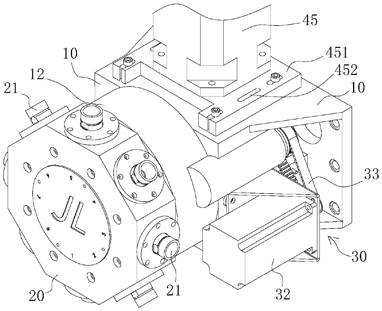
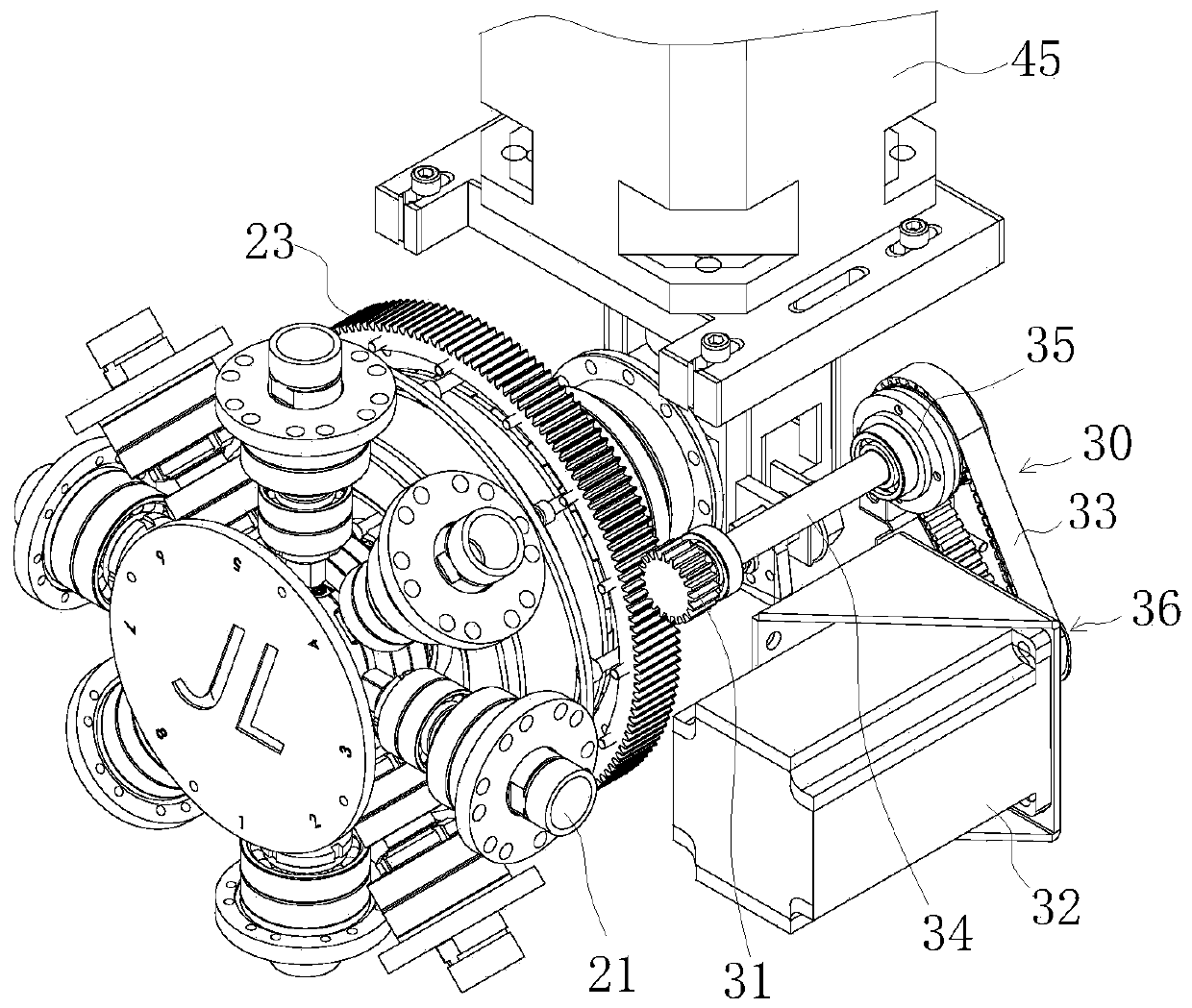
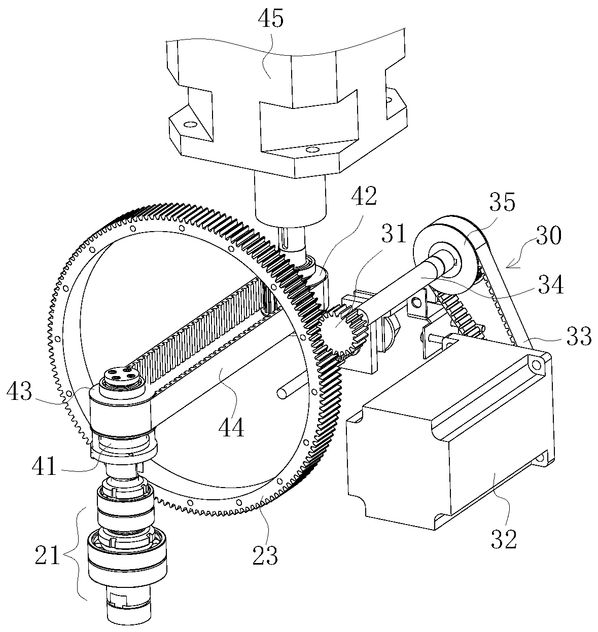
[0017] A cutting power system of a drilling and milling machining center, a plurality of cutting spindles 21 for clamping tools are arranged at intervals on the peripheral surface of a turret 20, and the rotary axis cores of each cutting spindle 21 are consistent with the radial direction of the turret 20 , the cutting power output shaft 41 is located in the middle of the chamber of the turret 20 and the axis direction of the cutting power output shaft 41 is consistent with the radial direction of the turret 20, and the cutting spindle 21 is indexed with the turret 20 to be coaxial with the cutting power output shaft 41 The inner end of the cutting spindle 21 and one end of the cutting power output shaft 41 form a mating fit between the projection and the groove when the position is in place, and the groove wall of the groove and the mating surface on the projection that cooperates with the groove wall Parallel to the plane of revolution of the turret 20 .

[0018] In the abov...


PUM


Abstract

The invention provides a cutting power system for a drilling and milling machining center. The cutting power system is characterized in that a plurality of cutting main shafts for clamping tools are arranged on the circumferential surface of a tool tower at intervals, a rotating shaft core of each cutting main shaft is consistent with the radial direction of the tool tower, cutting power output shafts are located in the middle of a cavity of the tool tower, the shaft core direction of the cutting power output shafts is consistent with the radial direction of the tool tower, when the cutting main shafts are rotated to the same core position as the cutting power output shafts along with the tool tower, the inner ends of the cutting main shafts and one ends of the cutting power output shaftsform mutual embedded matching between convex blocks and grooves, and the groove walls of the grooves and the matching surfaces on the convex blocks matched with the groove walls are parallel to the rotary surface of the tool tower. The timeliness of the tool changing response is improved, the timely combination and the timely separation of the cutting main shafts and the cutting power output shafts during each tool changing are ensured, and namely the accuracy of tool changing is ensured.

Description

technical field [0001] The invention belongs to the field of design and manufacture of numerical control machine tools, and in particular relates to a drilling and milling machining center. Background technique [0002] With the development of science and technology, the manufacturing industry has higher and higher requirements for machining precision. Traditional machining equipment has long been unable to meet the increasingly demanding process requirements. Therefore, CNC machine tools, a highly automated machining process, were born. Equipment, CNC machine tools adopt CNC system to automatically control the cutting, feeding and other actions of the machine tool, which can realize precise control of cutting amount and greatly improve production efficiency. The machining center is a CNC machine tool with a higher degree of automation. It can combine various processes such as milling and drilling, and realize cutting processing by combining the position adjustment of the wo...

Claims


Application Information

Patent Timeline
Patent Type & Authority Applications(China)
IPC IPC(8): B23Q3/157B23P23/02
CPCB23P23/02B23Q3/15706
Inventor 尹建贺蒋辉东郑胜华
Owner XUANCHENG JIANLIN MACHINERY
Why Eureka
Try Eureka