Drilling and milling machining center

A machining center, drilling and milling technology, applied in metal processing equipment, metal processing machinery parts, manufacturing tools, etc., can solve the problem of low position accuracy of the cutting spindle 23, difficulty in ensuring the alignment of tooth peaks and tooth valleys, and the influence of natural processing accuracy, etc. problem, to achieve the effect of ensuring timely combination and separation, simplifying the structure, and eliminating positioning errors

Pending Publication Date: 2020-05-12
XUANCHENG JIANLIN MACHINERY
View PDF0 Cites 9 Cited by
  • Summary
  • Abstract
  • Description
  • Claims
  • Application Information

AI Technical Summary

Problems solved by technology

In the above solution, when the gear 24 re-engages with the transition gear 41, it is difficult to ensure the alignment between the tooth peak and the tooth valley, which seriously affects the accuracy of the return after the tool change, that is, it is difficult to control the time-consuming of the tool change. When cutting, both rotation and axial displacement are required, the structure is complicated and the cumulative error is large. In addition, the rotation limit and axial limit are all dependent on the surface processing and matching accuracy of the toothed disc, so the position accuracy of the cutting spindle 23 is relatively low. Natural machining accuracy is severely affected

Method used


Image

  • Drilling and milling machining center
  • Drilling and milling machining center
  • Drilling and milling machining center

Examples


Embodiment Construction

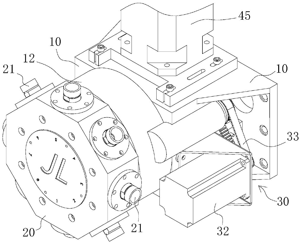
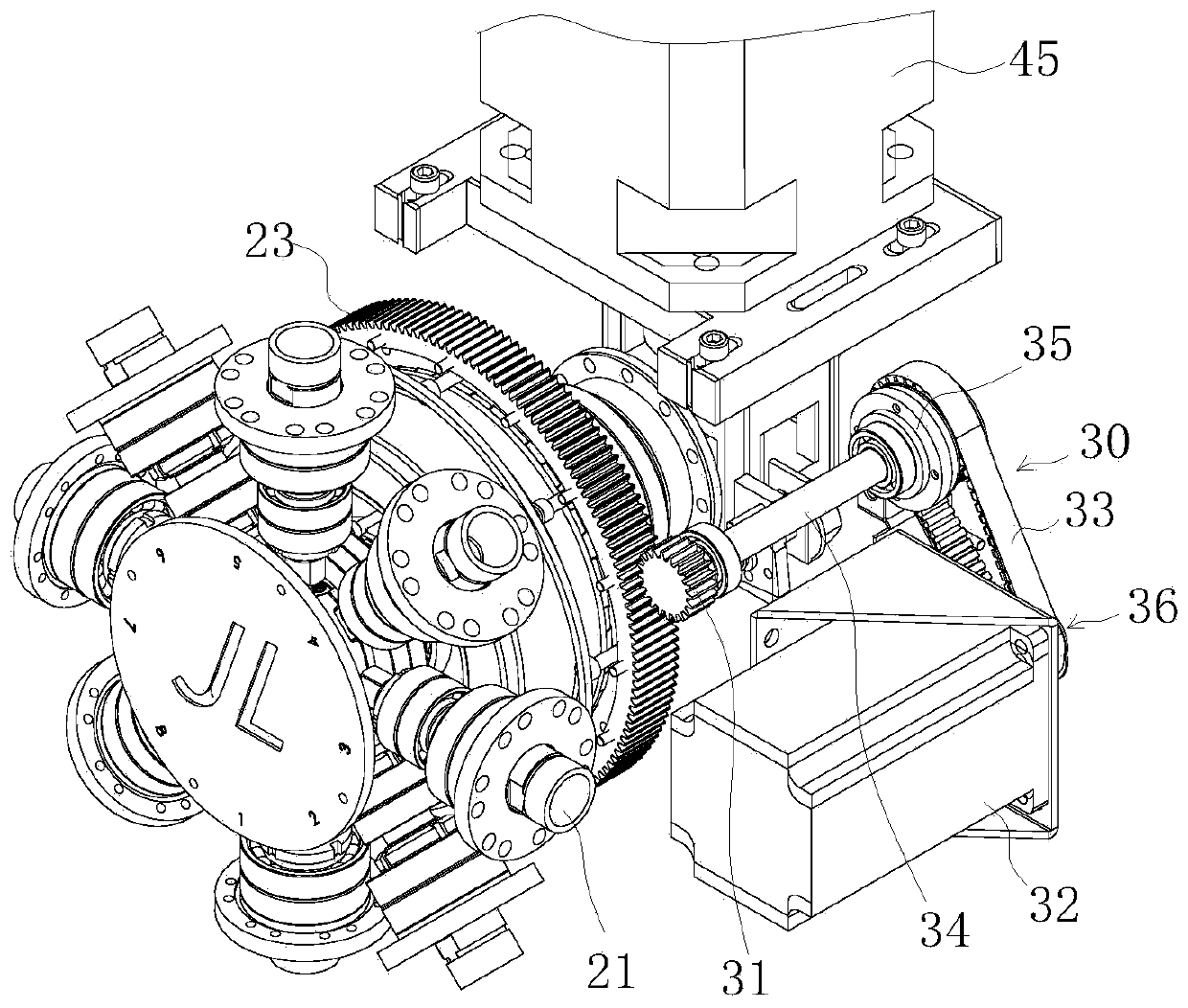
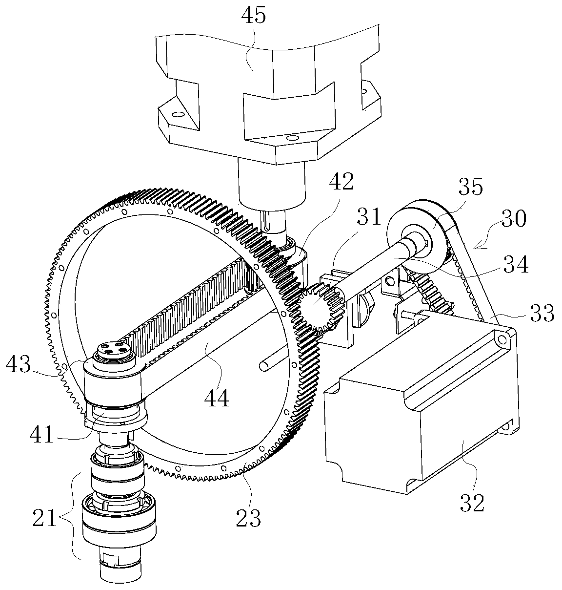
[0018] Such as figure 1 , 2 As shown in , 3 and 4, a drilling and milling machining center is provided with a turret 20 on the chassis 10 arranged on the frame, and the turret 20 and the chassis 10 form a circumferential rotation and axial limit cooperation, and the first drive unit 30 drives the turret 20 to rotate relative to the chassis 10 along the axis of rotation of the turret 20; this scheme limits the axial displacement of the turret 20, reduces the position error in the direction of one degree of freedom, and provides an axially determined position for the positioning of the tool. Locate the reference, and realize the conversion of the tool change position through the rotation of the turret 20 around its axis of rotation.

[0019] A locking mechanism is provided between the turret 20 and the chassis 10. When the locking mechanism is unlocked, the turret 20 rotates relative to the chassis 10 along the axis of rotation of the turret 20. When the locking mechanism is lo...


PUM


Abstract

The invention provides a drilling and milling machining center. A cutter tower is arranged on a case on a rack, the cutter tower and the case form peripheral rotation and axial limiting fit, and a first driving unit drives the cutter tower to rotate relative to the case along the revolving axis of a rotary tower. A locking mechanism is arranged between the cutter tower and the case, the cutter tower rotates relative to the case along the revolving axis of the rotary tower when the locking mechanism performs unlocking, and the rotation of the cutter tower relative to the case along the revolving axis of the rotary tower is limited when the locking mechanism performs locking. A plurality of main cutting shafts used for installing and clamping cutters are arranged on the circumferential faceof the cuter tower at intervals, the revolving axis cores of the main cutting shafts are consistent with the radial direction of the cutter tower, a cutting power output shaft is located in the middleof a cavity of the cutter tower, the axis core direction of the cutting power output shaft is consistent with the radial direction of the cutter tower, and the inner end of the main cutting shaft andone end of the cutting power output shaft form embedded cooperation of a protruding block and a groove when the main cutting shaft rotates to the position where the main cutting shaft and the cuttingpower output shaft share the same core position.

Description

technical field [0001] The invention belongs to the field of design and manufacture of numerical control machine tools, and in particular relates to a drilling and milling machining center. Background technique [0002] With the development of science and technology, the manufacturing industry has higher and higher requirements for machining precision. Traditional machining equipment has long been unable to meet the increasingly demanding process requirements. Therefore, CNC machine tools, a highly automated machining process, were born. Equipment, CNC machine tools adopt CNC system to automatically control the cutting, feeding and other actions of the machine tool, which can realize precise control of cutting amount and greatly improve production efficiency. The machining center is a CNC machine tool with a higher degree of automation. It can combine various processes such as milling and drilling, and realize cutting processing by combining the position adjustment of the wo...

Claims


Application Information

Patent Timeline
Patent Type & Authority Applications(China)
IPC IPC(8): B23Q3/157B23P23/02
CPCB23P23/02B23Q3/15706
Inventor 蒋辉东尹建贺郑胜华
Owner XUANCHENG JIANLIN MACHINERY
Why Eureka
Try Eureka