
Turbine furnace shell

A technology of furnace shell and turbine, which is applied in the direction of household furnace/stove, furnace/stove base, household heating, etc. It can solve the problems of reducing the service life of gas stoves, reducing the combustion firepower of gas stoves, and the loss of users' lives and property. Large firepower, sufficient combustion, and the effect of improving the thermal efficiency of combustion

Pending Publication Date: 2020-05-12
浙江博立灶具科技有限公司
View PDF0 Cites 1 Cited by
  • Summary
  • Abstract
  • Description
  • Claims
  • Application Information

AI Technical Summary

Problems solved by technology

[0003] Traditional commercial gas stoves have only gas supply and no air supply inside the small fire, while there are both gas supply and air supply inside the big fire. Oxygen around the core, so a small fire that only relies on oxygen around the core for combustion is likely to burn weakly or go out directly due to insufficient oxygen supply, and it is easy to extinguish when there is air blowing outside or liquid dripping during cooking
After the low fire is extinguished, not only the overall combustion firepower of the gas stove is reduced, but also when the high fire needs to be adjusted back to low fire, the low fire is not easy to ignite, which will directly cause the gas stove to go out as a whole, and it needs to be re-ignited to continue cooking, reducing the gas stove. If the gas stove is not turned off in time after the overall extinguishment, it will easily cause safety hazards and bring loss of life and property to users

Method used


Image

  • Turbine furnace shell
  • Turbine furnace shell
  • Turbine furnace shell

Examples


Embodiment Construction

[0027] The present invention will be described in further detail below in conjunction with the accompanying drawings.

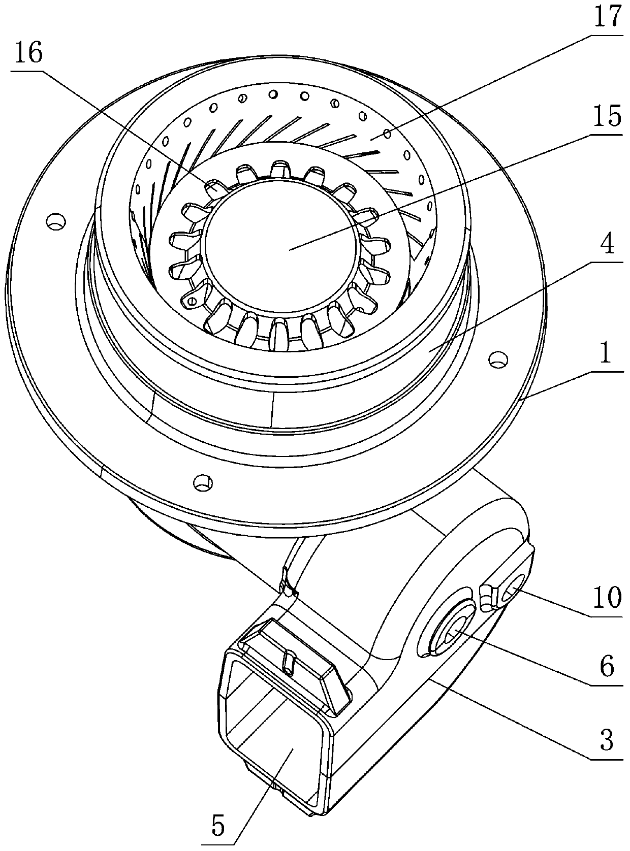
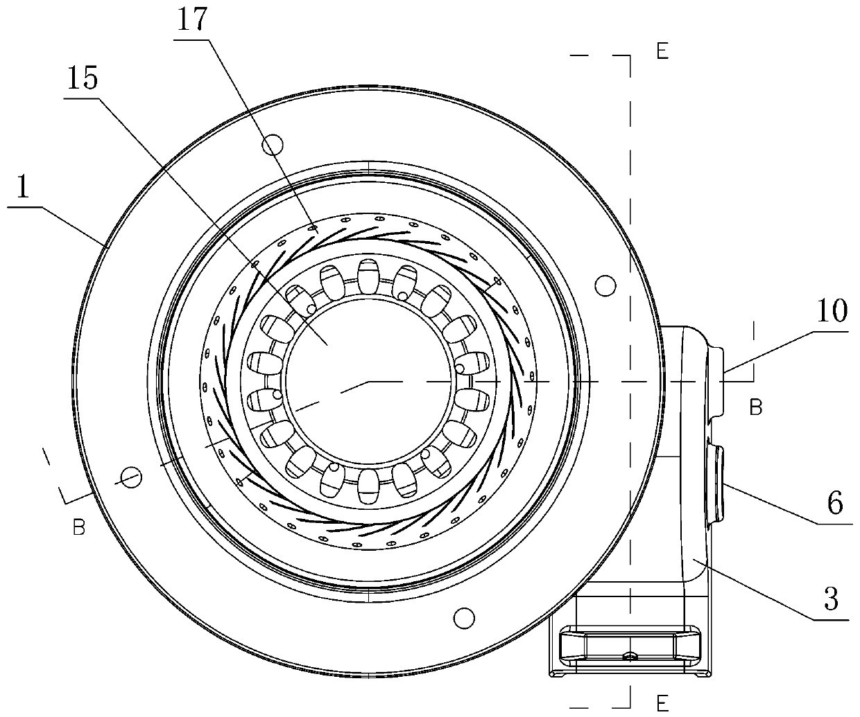
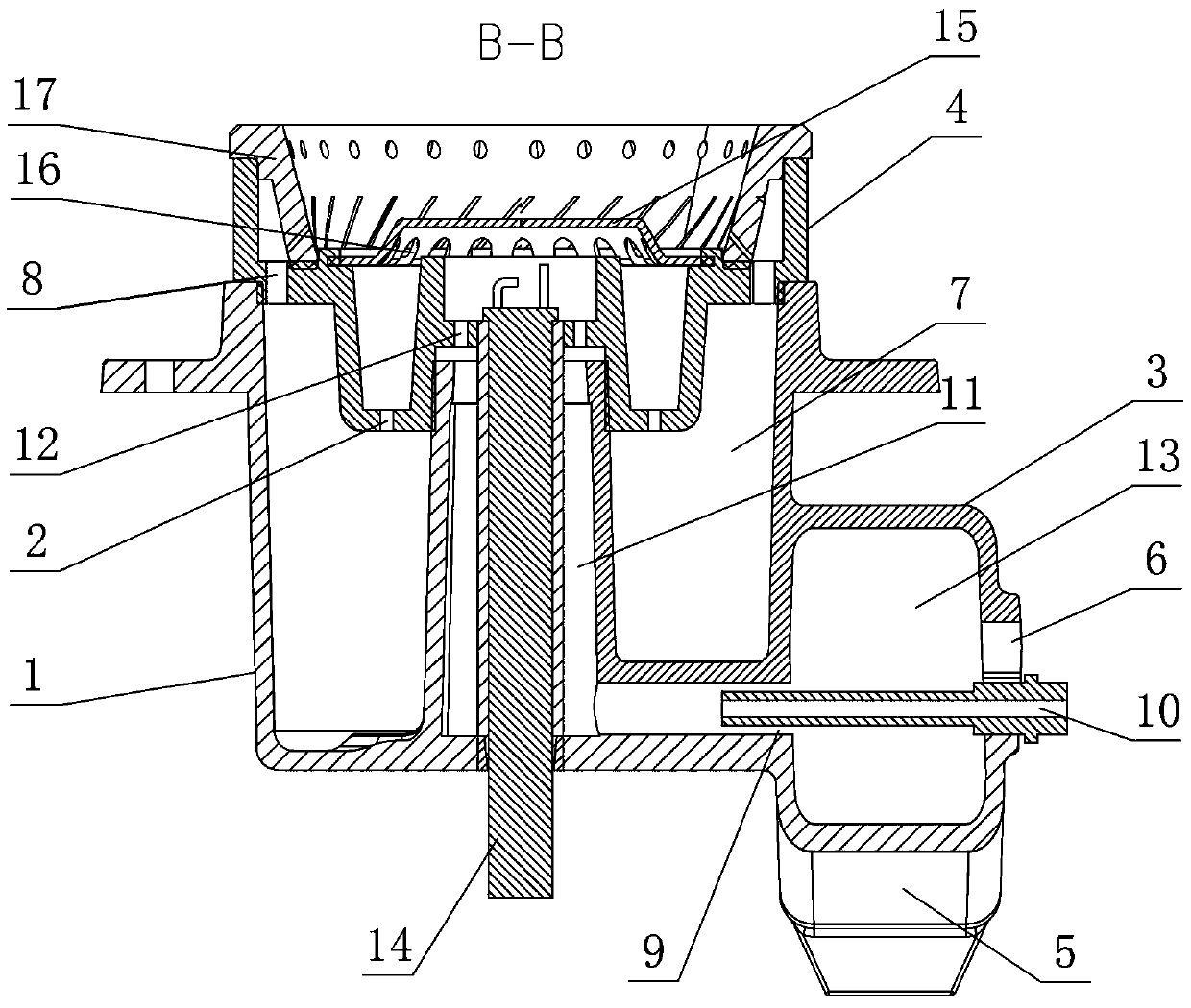
[0028] Such as Figure 1-4 As shown, a turbine furnace shell includes a furnace shell body 1 , a turbine-shaped ejector tube 3 arranged on one side of the furnace shell body 1 and a furnace core 4 covered on the top of the furnace shell body 1 . The furnace shell body 1 is provided with a large fire channel and a small fire channel; the large fire channel includes an air inlet 5 for air intake, a large fire air inlet 6 for supplying gas to the large fire flow channel 7, and air and gas The large fire runner 7 and the large fire vent 8 that the gas and air mixture are passed out. The small fire passage includes a small fire air supply port 9 for supplying air to the small fire flow channel 11, a small fire air inlet 10 for supplying gas to the small fire flow channel 11, and a small fire flow channel for passing air and gas. 11 and fuel gas and air mixture g...


PUM


Abstract

The invention belongs to the technical field of gas stove furnace shells, and particularly relates to a turbine furnace shell. The turbine furnace shell includes a furnace shell body, a turbine-shapedejector tube arranged on one side of the furnace shell body and a furnace core covered on the top of the furnace shell body. A high fire channel and a low fire channel are arranged in the furnace shell body. The high fire channel includes an air inlet, a high fire air inlet, a high fire flow channel and a plurality of high fire air outlets. The low fire channel includes a low fire air supply portfor supplying air to a low fire flow channel, a low fire air inlet, the low fire flow channel and a plurality of low fire air outlets. The low fire flow channel is arranged at the center of the furnace shell body, the high fire flow channel is arranged on the outer circle of the low fire flow channel in a surrounding mode, the top end of the low fire flow channel and the top end of the high fireflow channel are connected with the furnace core, the multiple high fire air outlets are evenly formed in the connection position of the furnace core and the high fire flow channel, and the multiple low fire air outlets are evenly formed in the connection position of the furnace core and the low fire flow channel. The low-fire combustion is more stable, the overall combustion fire force is stronger, and the service life is longer.

Description

technical field [0001] The invention belongs to the technical field of gas stove shells, and in particular relates to a turbine shell. Background technique [0002] Gas stove has become a kind of widely used kitchen utensils, is the kitchen utensils that carry out direct fire heating with gaseous fuels such as artificial coal gas, natural gas. During the use of the gas stove, it is necessary to manually adjust the size of the flame and control the heat to match the cooking. When the gas stove is working, it is first ignited by the small fire in the inner circle of the induction ignition needle, and then ignites the big fire in the outer circle with the small fire. [0003] Traditional commercial gas stoves have only gas supply and no air supply inside the small fire, while there are both gas supply and air supply inside the big fire. Oxygen around the core, so a small fire that only relies on oxygen around the core for combustion is likely to burn weakly or go out directly...

Claims


Application Information

Patent Timeline
IPC IPC(8): F24C15/08F24C3/08F24C3/12
CPCF24C3/085F24C3/126F24C15/08
Inventor 鞠木春方明
Owner 浙江博立灶具科技有限公司
Learn More