Circuit and device for detecting temperature of reference voltage bjt tube

A technology for detecting benchmarks and voltages, applied in the direction of adjusting electrical variables, control/regulating systems, instruments, etc., can solve the problems of large temperature value error, damaged circuits, etc., to achieve the effect of protecting the chip

Active Publication Date: 2020-05-12
ETOWNIP MICROELECTRONICS BEIJING CO LTD
View PDF5 Cites 1 Cited by
  • Summary
  • Abstract
  • Description
  • Claims
  • Application Information

AI Technical Summary

Problems solved by technology

[0002] The chip in the circuit will continue to emit heat during work, which will cause the circuit temperature to be too high and damage the circuit
In the prior art, the temperature detection device is mainly used for detection, and the temperature value obtained by this method has a large error

Method used


Image

  • Circuit and device for detecting temperature of reference voltage bjt tube
  • Circuit and device for detecting temperature of reference voltage bjt tube
  • Circuit and device for detecting temperature of reference voltage bjt tube

Examples


Embodiment Construction

[0022] In order to make the technical problems solved by the present invention, the technical solutions adopted and the technical effects achieved clearer, the technical solutions of the embodiments of the present invention will be further described in detail below in conjunction with the accompanying drawings. Apparently, the described embodiments are only some of the embodiments of the present invention, but not all of them. Based on the embodiments of the present invention, all other embodiments obtained by persons of ordinary skill in the art without making creative efforts belong to the protection scope of the present invention.

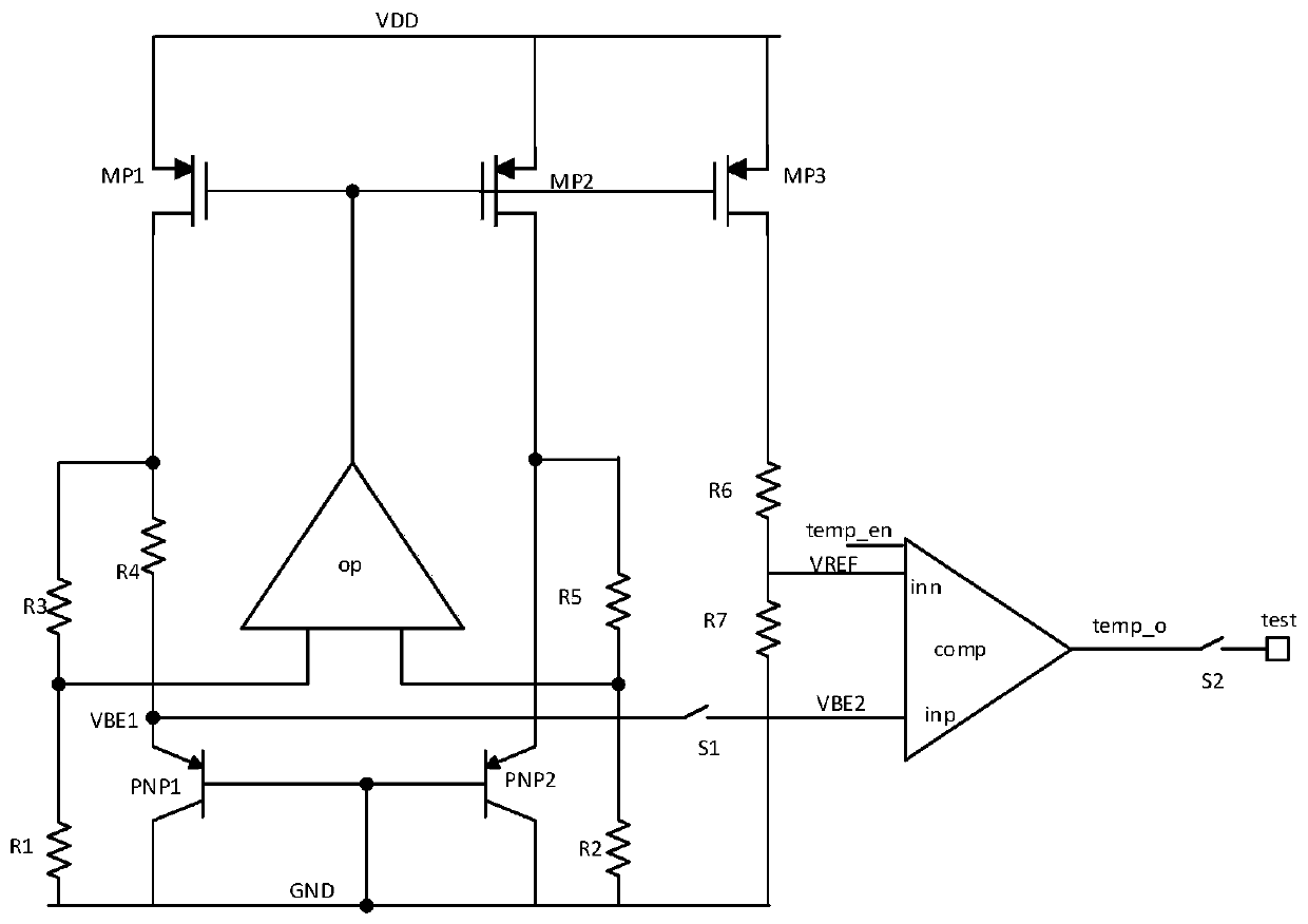
[0023] A circuit for detecting the junction temperature of a reference voltage bjt tube provided by the present invention comprises: transistors MP1, MP2 and MP3, triodes PNP1 and PNP2, resistors R1, R2, R3, R4, R5, R6 and R7, operational amplifier op, comparison tor comp, switches S1 and S2. For specific connections, see figure 1 : The base o...


PUM


Abstract

The invention provides a circuit for detecting a reference voltage bjt tube section temperature, which is characterized in that a PNP1 base electrode is connected with a PNP2 base electrode to the ground, and a PNP1 emitting electrode is connected with a first end of an R4; the second end of R4 and the second end of R3 are connected to the drain electrode of MP1; the first end of R3 and the secondend of R1 are connected to the first input end of OP; the emitter of the PNP2 and the second end of the R5 are connected to the drain of the MP2; the first end of R5 and the second end of R2 are connected to the second input end of OP; the grid electrode of the MP1, the grid electrode of the MP2 and the grid electrode of the MP3 are all connected to an OP output end; the source electrode of the MP1, the source electrode of the MP2 and the source electrode of the MP3 are connected with a power supply VDD; the drain electrode of the MP3 is connected with the second end of the R6; the first endof R2, the collector electrode of PNP2, the collector electrode of PNP1, the first end of R1 and the first end of R7 are all connected with a circuit ground GND; the first end R6 and the second end R7are connected with the negative end of the comparator; the voltage VBE1 between the base electrode and the emitting electrode of the PNP1 is transmitted to the positive end VBE2 of the comparator through the switch S1; and an output signal temp _ o of the comparator is connected to the test pad through S2. According to the invention, the temperature-saving working temperature of the BJT tube canbe indicated, so that the temperature of the chip can be indicated and alarmed.

Description

technical field [0001] The invention belongs to the technical field of integrated circuits, and in particular relates to a circuit and a device for detecting the junction temperature of a reference voltage bjt tube. Background technique [0002] The chip in the circuit will continuously emit heat during operation, which will cause the circuit temperature to be too high and damage the circuit. In the prior art, the detection is mainly performed by a temperature detection device, and the temperature value obtained by this method has a large error. [0003] At present, the bandgap reference circuit, as an important component module of the integrated circuit chip, is widely used in various types of SOC chips. The bandgap reference module can provide the required reference voltage and reference current for the system. The bandgap reference module is a basic module and a subunit of the SOC chip. The general working range of the bandgap reference module can work at -40°-125°. Si...

Claims


Application Information

Patent Timeline
Patent Type & Authority Applications(China)
IPC IPC(8): G05F1/567
CPCG05F1/567
Inventor 丁玲朱敏
Owner ETOWNIP MICROELECTRONICS BEIJING CO LTD
Why Eureka
Try Eureka