Dynamic modeling method for aircraft high-lift system

A technology of system dynamics and modeling method, which is applied in the field of aircraft high-lift system dynamics modeling, can solve the problems of high-lift system such as poor economy, high price, and high protection threshold, so as to solve the bottleneck problem of development and facilitate the solution , the effect of less model degrees of freedom

Active Publication Date: 2020-05-12
XIAN AIRCRAFT DESIGN INST OF AVIATION IND OF CHINA
View PDF21 Cites 1 Cited by
  • Summary
  • Abstract
  • Description
  • Claims
  • Application Information

AI Technical Summary

Problems solved by technology

The high-lift systems of the ARJ21-700 aircraft and C919 aircraft developed in my country generally purchase shelf products from well-known foreign suppliers. Foreign suppliers generally do not disclose the dynamic design of the high-lift systems with technical secrets. Such aircraft high-lift systems often The high-lift system is much heavier than the actual requirements of the aircraft design, and the load protection threshold of the actuating parts and driving parts is high. The high-lift system is not economical and the price is very expensive.

Method used


Image

  • Dynamic modeling method for aircraft high-lift system
  • Dynamic modeling method for aircraft high-lift system
  • Dynamic modeling method for aircraft high-lift system

Examples


Embodiment Construction

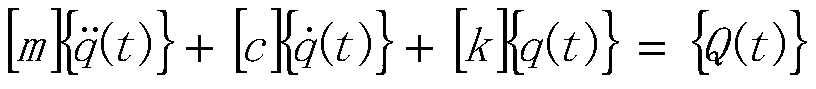
[0024] A method for modeling dynamics of an aircraft high-lift system, comprising the following steps:

[0025] Step 1: Calculate the stiffness k of all torsion tubes between the individual actuators eq , the calculation formula is: in G is the shear modulus of the torque tube material, I i is the moment of inertia of the cross-section of the i-th torsion tube, L i is the length of the i-th torque tube.

[0026] Step 2: Establish a mathematical model of the reducer in the transmission line;

[0027] The mathematical model of the reducer in the transmission line is: In the formula, θ in (t) is the angular displacement of the input end of the reducer, n is the reduction ratio of the reducer, θ out (t) is the angular displacement of the output end of the reducer, is the angular acceleration at the input end of the reducer, is the angular acceleration at the output end of the reducer.

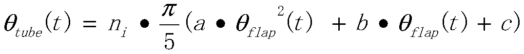
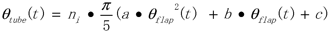
[0028] Step 3: Establish a combined mathematical model of the composite mechanis...


PUM


Abstract

The invention discloses a dynamic modeling method for an aircraft high-lift system. The dynamic modeling method comprises the steps of: 1, calculating rigidity keq of all torque tubes between actuators; 2, establishing a mathematical model of a speed reducer in the transmission line system; 3, establishing a combined mathematical model of a composite mechanism between the transmission line systemand the high lift device; 4, calculating the rotational inertia of each composite mechanism and flap; and step 5, carrying out dynamic analysis by using a Lagrange method and the like. The dynamic model of the high-lift system is established, the dynamics problem in the development of the aircraft high-lift system is solved, an accurate fault mechanism can be provided for faults in an iron bird test, in the design of the high-lift system, the key problems of speed reducer protection threshold design, system fault load calculation and the like are solved, the development efficiency is improved,the cost of the high-lift system is greatly reduced, and the development bottleneck problem is solved.

Description

technical field [0001] The invention belongs to the technical field of aircraft high-lift system dynamics design and verification, and in particular relates to an aircraft high-lift system dynamics modeling method. Background technique [0002] Large jet transport aircraft and passenger aircraft require efficient high-lift systems and high-lift devices. The design of high-lift systems is the design content of modern aircraft. Since the mass of the high-lift device is often large, the dynamic effect cannot be ignored in the design, and failures or problems caused by dynamic factors are often encountered during ground tests and flights. The high-lift systems of the ARJ21-700 aircraft and C919 aircraft developed in my country generally purchase shelf products from well-known foreign suppliers. Foreign suppliers generally do not disclose the dynamic design problems of the high-lift systems with technical secrets. Such aircraft high-lift systems often The high-lift system is much...

Claims


Application Information

Patent Timeline
Patent Type & Authority Applications(China)
IPC IPC(8): G06F30/20G06F30/15G06F119/14
CPCY02T90/00
Inventor 左朋杰于安元张晓翠张伟涛陈松松
Owner XIAN AIRCRAFT DESIGN INST OF AVIATION IND OF CHINA
Why Eureka
Try Eureka