A Spin Speed Control Method for Space Flexible Electric Sail
A control method and flexible electric technology, applied in the field of electric sails, can solve problems such as speed regulation control of flexible cable spin multi-body systems that cannot realize flexible electric sails, and achieve the effect of convenient coupling modeling
- Summary
- Abstract
- Description
- Claims
- Application Information
AI Technical Summary
Problems solved by technology
Method used
Image
Examples
specific Embodiment approach 1
[0022] Specific implementation mode 1: A method for controlling the spin speed of a space flexible electric sail given in this implementation mode specifically includes the following steps:
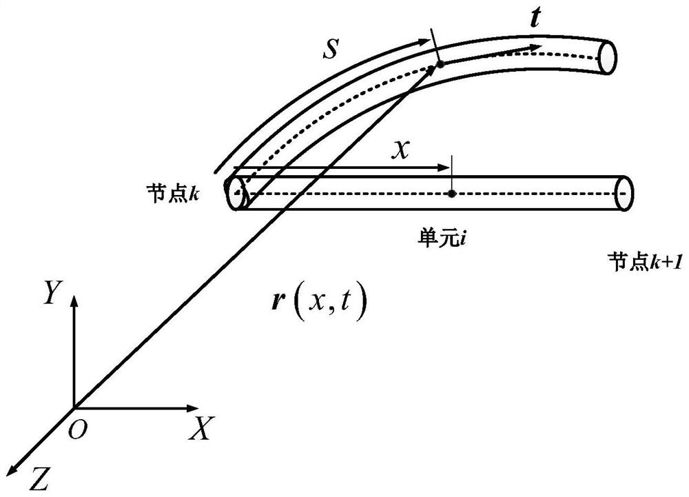
[0023] Step 1: First establish the absolute reference coordinate system of space, such as figure 1 As shown, the large deformation dynamic model of flexible cable is established based on the absolute node coordinate method, the element node is determined, and the position, rotation, and deformation are described by six degrees of freedom node coordinates. The position of any point on the beam element is determined by the generalized coordinates according to the shape function ( Absolute node coordinates) means that the constant mass matrix and the generalized elastic force under the reference configuration are deduced with the unit node position and position gradient as generalized variables;
[0024] Step 2: Select the position of the central rigid body and the quaternion as the generali...
specific Embodiment approach 2
[0027] Specific implementation mode 2: the difference between this implementation mode and specific implementation mode 1 is that step 1 is specifically as follows: figure 1 As shown in the figure, establish the space absolute reference coordinate system OXYZ, under the space absolute reference coordinate system OXYZ, carry out the physical discretization of the cable, express the degree of freedom of the beam element at the nodes at both ends, and use the node coordinates of six degrees of freedom to describe each element node j degrees of freedom:
[0028]
[0029] In formula (1), q j is the generalized coordinate of the unit node j, x is the coordinate of the unit substance described in the reference configuration, is the position gradient, k=1,2,3, r 1 j , is the component of r;
[0030] The position of any point on the beam element is represented by generalized coordinates according to the shape function:
[0031] r=S(x)q (2)
[0032] For a unit of length L, t...
specific Embodiment approach 3
[0050] Specific embodiment three: the difference between this embodiment and specific embodiment two is: in step two, the process of establishing the central rigid body dynamics model is specifically:
[0051] Let the generalized coordinates of the rigid body be:
[0052] q c =[q r ,Θ]=[q x q y q z θ 0 θ 1 θ 2 θ 3 ] (9)
[0053] Among them, q r is the rigid body displacement coordinates, Θ is the attitude quaternion, Θ is determined by θ 0 , θ 1 , θ 2 , θ 3 Quaternary composition, q x ,q y ,q z Respectively represent the X-axis, Y-axis, Z-axis displacement coordinates of the rigid body;
[0054] Calculate the kinetic energy of the rigid body T h :
[0055]
[0056] In formula (10) is the attitude quaternion matrix, m c is the mass of the central rigid body, V c is the velocity vector of the central rigid body, J is the moment of inertia matrix of the central rigid body, ω is the rotational angular velocity vector of the central rigid body, is ...
PUM
 Abstract
Description
Claims
Application Information
 - R&D
- Intellectual Property
- Life Sciences
- Materials
- Tech Scout
- Unparalleled Data Quality
- Higher Quality Content
- 60% Fewer Hallucinations
Browse by: Latest US Patents, China's latest patents, Technical Efficacy Thesaurus, Application Domain, Technology Topic, Popular Technical Reports.
© 2025 PatSnap. All rights reserved.Legal|Privacy policy|Modern Slavery Act Transparency Statement|Sitemap|About US| Contact US: help@patsnap.com


