Efficient box-type transformer cooling device

A box-type transformer and cooling device technology, which is applied in the direction of transformer/inductor casing, transformer/inductor cooling, transformer/inductor parts, etc., which can solve the problems of failure to meet the use requirements, internal parts damage, and small heat dissipation range, etc. problems, to avoid excessive temperature in the working environment, improve the service life, and quickly cool down the temperature

Inactive Publication Date: 2020-05-12
河南省森电智能装备有限公司
View PDF0 Cites 2 Cited by
  • Summary
  • Abstract
  • Description
  • Claims
  • Application Information

AI Technical Summary

Problems solved by technology

[0003] At present, box-type transformers are mostly placed outdoors during use, and will be affected by the external environment. If the external temperature is too high, the internal temperature of the box-type transformer will rise rapidly, resulting in damage to internal parts. , it will lead to problems such as spontaneous combustion in serious cases, so it is urgent to carry out heat dissipation treatment, but the heat dissipation of the existing heat dissipation device is only carried out by the heat dissipation fan, and the heat dissipation fan is generally a fixed structure, and the heat dissipation effect is high when the temperature is too high. At the same time, it is not obvious, and the range of heat dissipation is also small, which cannot meet the current use requirements

Method used


Image

  • Efficient box-type transformer cooling device
  • Efficient box-type transformer cooling device
  • Efficient box-type transformer cooling device

Examples


Embodiment Construction

[0020] The following will clearly and completely describe the technical solutions in the embodiments of the present invention with reference to the accompanying drawings in the embodiments of the present invention. Obviously, the described embodiments are only some, not all, embodiments of the present invention. Based on the embodiments of the present invention, all other embodiments obtained by persons of ordinary skill in the art without making creative efforts belong to the protection scope of the present invention.

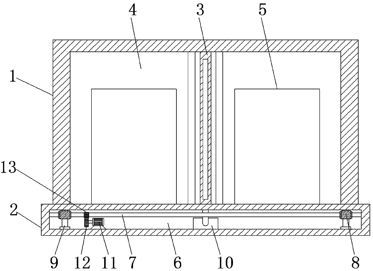
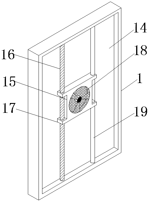
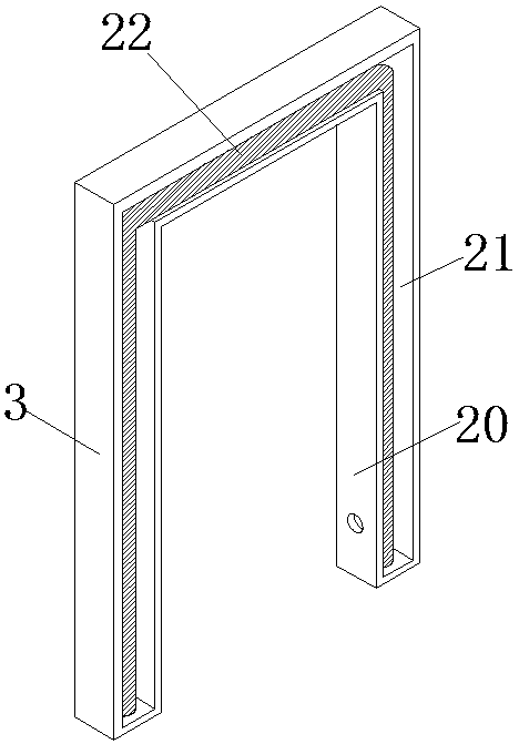
[0021] The present invention provides such as Figure 1-4 A high-efficiency box-type transformer cooling device shown includes a device housing 1 and a base 2, the device housing 1 is fixedly installed at the middle position on the base 2, the device housing 1 has a rectangular box-shaped structure, and the inside of the device housing 1 The middle position of the center is divided into two groups of equal-sized placement cavities 4 through vertical partitions...


PUM


Abstract

The invention discloses an efficient box-type transformer heat dissipation device. The device comprises a device shell and a base, and the device shell is fixedly installed in the middle of the base.The device shell is of a cuboid box-shaped structure. The middle position of the interior of the device shell is divided into two groups of placement cavities with the same size through a vertical partition plate; a transformer body is mounted in the middle of each of the two groups of placement cavities; and side grooves are formed in the set of inner walls, corresponding to the partition plates,of the placement cavities. Matched heat dissipation fan mounting plates are mounted in the side grooves; cooling fans are embedded in the side face, facing the transformer body, of the heat dissipation fan mounting plates, protruding blocks are arranged at the four corners of the heat dissipation fan mounting plates in a protruding mode, the two sets of protruding blocks on one side are arrangedon the side grooves in a lifting mode through transmission assemblies, and the two sets of protruding blocks on the other side are connected with guide assemblies facilitating lifting of the protruding blocks. According to the efficient box-type transformer heat dissipation device, through double heat dissipation of the cooling fans and the refrigeration assembly, the heat dissipation effect is faster, and meanwhile heat dissipation is more comprehensive.

Description

technical field [0001] The invention belongs to the technical field of high-efficiency box-type transformers, and in particular relates to a cooling device for high-efficiency box-type transformers. Background technique [0002] Box-type transformer, also known as prefabricated substation or prefabricated transformer. It is a kind of high-voltage switchgear, distribution transformer and low-voltage power distribution device. It is a factory prefabricated indoor and outdoor compact power distribution device arranged according to a certain wiring scheme, which is to organically combine functions such as transformer step-down and low-voltage power distribution. Together, it is installed in a moisture-proof, rust-proof, dust-proof, rodent-proof, fire-proof, theft-proof, heat-insulated, fully enclosed, and movable steel structure box, which is especially suitable for urban network construction and transformation. It is a rising after the civil transformer. A brand new transforme...

Claims


Application Information

Patent Timeline
Patent Type & Authority Applications(China)
IPC IPC(8): H01F27/02H01F27/08H01F27/16
CPCH01F27/025H01F27/085H01F27/16
Inventor 李勇贾鑫鑫蒋红娅张旭
Owner 河南省森电智能装备有限公司
Why Eureka
Try Eureka