Solar photovoltaic power generation device

A technology of solar photovoltaic and power generation devices, applied in the field of solar photovoltaic power generation, can solve the problems of complex structure of solar photovoltaic panels, time-consuming, easily damaged photovoltaic panels, etc., and achieve the effect of simple and reliable structure, convenient storage and transfer, and safe and convenient use

Active Publication Date: 2020-05-12
俞锦澜
View PDF15 Cites 10 Cited by
  • Summary
  • Abstract
  • Description
  • Claims
  • Application Information

AI Technical Summary

Problems solved by technology

[0004] However, in the existing production and life, the folding and storage structure of solar photovoltaic panels is complicated, and it is necessary to install support frames after unfolding, which is time-consuming and easy to damage the photovoltaic panels

Method used


Image

  • Solar photovoltaic power generation device
  • Solar photovoltaic power generation device
  • Solar photovoltaic power generation device

Examples


Embodiment 1

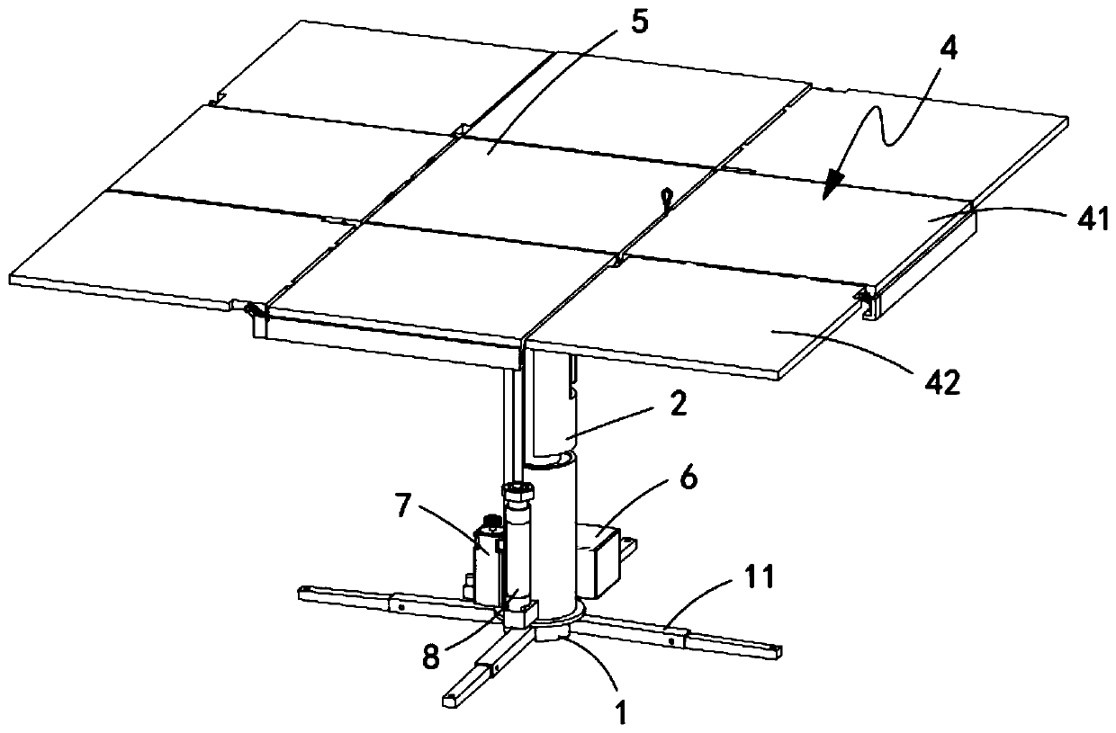
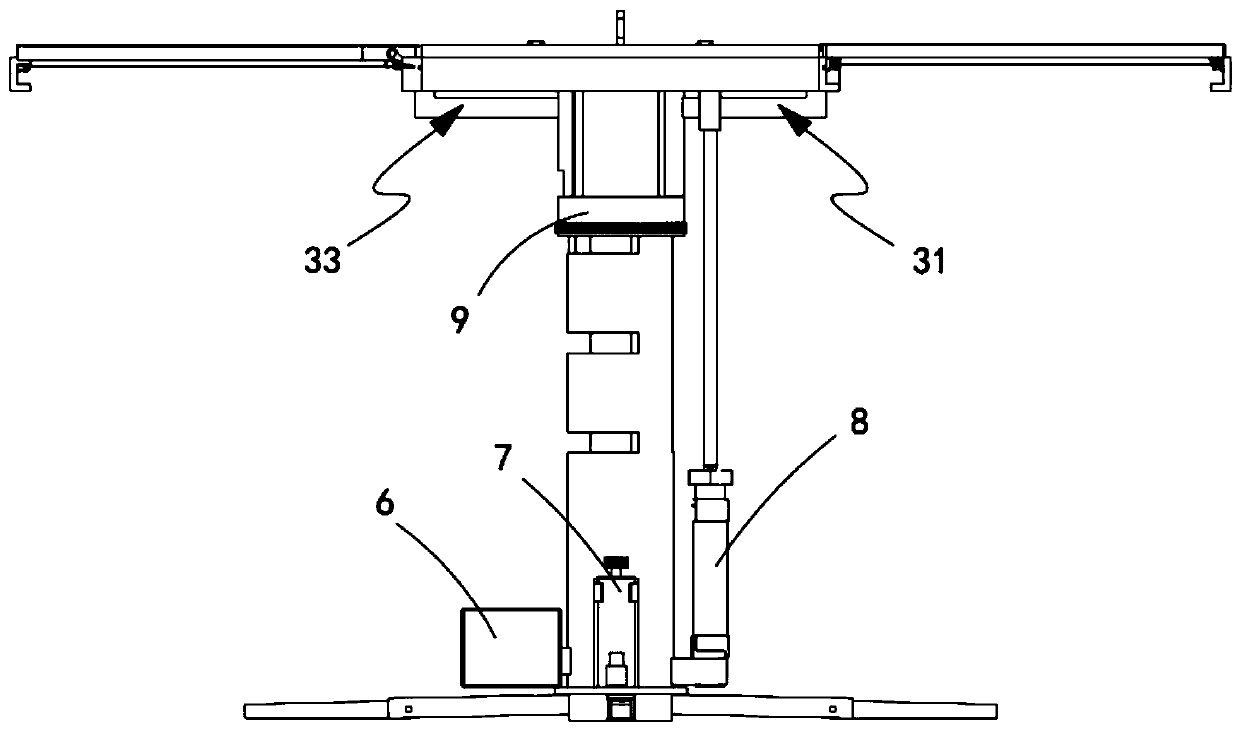
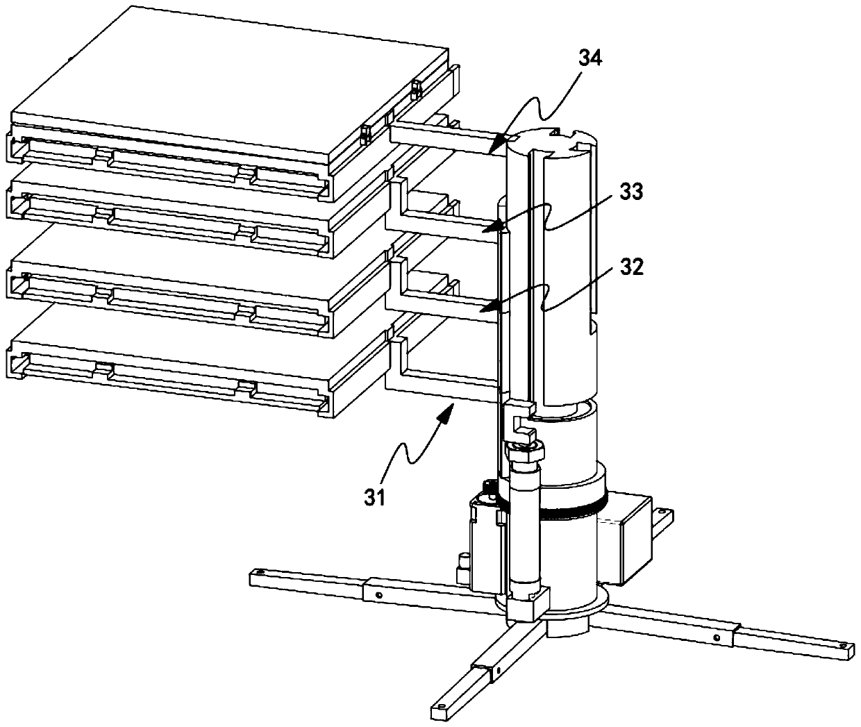
[0057] Embodiment 1: as Figure 1-5 As shown, the present invention provides a technical solution, a solar photovoltaic power generation device, including a fixed base 1, the upper end surface of the fixed base 1 is provided with a control box 6, a drive motor 7 and a cylinder 8, characterized in that: the fixed base 1 is fixedly provided with a support device 2 along its axis, and one side of the support device 2 in the axial direction is respectively provided with a photovoltaic panel support assembly a31, a photovoltaic panel support assembly b32, a photovoltaic panel support assembly c33, and a photovoltaic panel support assembly d34. The ends of the photovoltaic panel support assembly a31, photovoltaic panel support assembly b32, photovoltaic panel support assembly c33, and photovoltaic panel support assembly d34 are fixedly connected with photovoltaic panel assemblies 4, and the photovoltaic panel assembly 4 on the photovoltaic panel support assembly d34 is A central pho...

Embodiment approach

[0069] Such as Figure 11 and Figure 12 As shown, as a preferred implementation, the photovoltaic panel support assembly a31 includes:

[0070] A sliding head 311, the sliding head 311 is arranged at one end of the photovoltaic panel support assembly a31 relatively away from the photovoltaic panel assembly 4, and the sliding head 311 is slidably arranged in the first sliding groove 21; and

[0071] A fan-shaped plate a312 , the fan-shaped plate a312 is arranged at an end of the photovoltaic panel support assembly a31 close to the sliding head 311 , and the fan-shaped plate a312 covers the supporting device 2 .

[0072] Such as Figure 13 and Figure 14 As shown, as a preferred embodiment, the photovoltaic panel support assembly b32 and the photovoltaic panel support assembly c33 both include:

[0073] Sliding head 311, the sliding head 311 is arranged at the end of the photovoltaic panel support assembly b32 and the photovoltaic panel support assembly c33 that is relative...


PUM


Abstract

The invention discloses a solar photovoltaic power generation device. The device comprise a fixed base, and a control box, a driving motor and an air cylinder are arranged on the upper end surface ofthe fixed base; a supporting device is fixedly arranged on the fixed base along the axis of the fixed base; a photovoltaic panel supporting assembly a, a photovoltaic panel supporting assembly b, a photovoltaic panel supporting assembly c and a photovoltaic panel supporting assembly d are arranged on one side of the supporting device in the axis direction; photovoltaic panel assemblies are fixedlyconnected to the ends of the photovoltaic panel supporting assemblies, a central photovoltaic panel is hinged to the photovoltaic panel assembly on the photovoltaic panel supporting assembly d, and the control box, the driving motor and the air cylinder are arranged on the outer edge of the fixed base in a surrounding mode. By means of movement of the photovoltaic panel supporting assembly a, thephotovoltaic panel supporting assembly b and the photovoltaic panel supporting assembly c, the device becomes a nine-square-grid power generation plane when being unfolded, the photovoltaic panel isstored on one side of the supporting device when being contracted, and the effect that the solar photovoltaic panel is convenient to store and unfold is effectively achieved.

Description

technical field [0001] The invention relates to the technical field of solar photovoltaic power generation, in particular to a solar photovoltaic power generation device. Background technique [0002] Photovoltaic power generation is based on the principle of photovoltaic effect, using solar cells to directly convert sunlight energy into electrical energy. Regardless of whether it is used independently or connected to the grid, the photovoltaic power generation system is mainly composed of three parts: solar panels (components), controllers and inverters. They are mainly composed of electronic components, but do not involve mechanical parts. Therefore, photovoltaic power generation equipment is extremely refined, reliable, stable, long-life, and easy to install and maintain. Theoretically speaking, photovoltaic power generation technology can be used in any occasion that needs power, ranging from spacecraft to household power, large megawatt power stations, and small toys. ...

Claims


Application Information

Patent Timeline
Patent Type & Authority Applications(China)
IPC IPC(8): H02S30/20H02S20/30F24S30/00
CPCF24S30/00H02S20/30H02S30/20Y02E10/47Y02E10/50
Inventor 俞锦澜
Owner 俞锦澜
Why Eureka
Try Eureka