Three-phase separation device for water quenching product and water quenching flue gas treatment system and method

A flue gas treatment system and three-phase separation technology, applied in the field of water quenching, can solve the problems of explosion hazards, environmental protection issues, and no efficient and energy-saving treatment technology, etc., to achieve strong practicability, simple structure, and improved water quenching efficiency Effect

Pending Publication Date: 2020-05-15
CHENGDU INTERMENT TECH
View PDF0 Cites 1 Cited by
  • Summary
  • Abstract
  • Description
  • Claims
  • Application Information

AI Technical Summary

Problems solved by technology

However, a large amount of water-quenched flue gas with high temperature and high pressure characteristics will be produced during the water quenching process. On the one hand, if these water-quenched flue gases are not properly handled in time, there will be explosion hazards. On the other hand, the collected water-quenched flue gas There is no efficient and energy-saving treatment technology for the resulting environmental problems

Method used


Image

  • Three-phase separation device for water quenching product and water quenching flue gas treatment system and method
  • Three-phase separation device for water quenching product and water quenching flue gas treatment system and method
  • Three-phase separation device for water quenching product and water quenching flue gas treatment system and method

Examples


Embodiment 1

[0045] The three-phase separation device and water quenching flue gas treatment system for water quenching products in this embodiment are as follows: figure 1 shown.

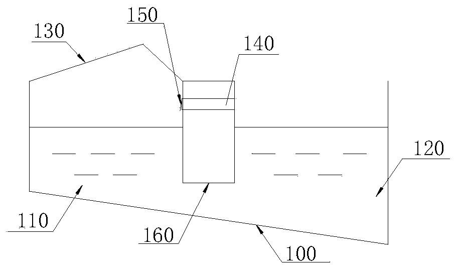
[0046] Such as figure 1 As shown, the three-phase separation device for water-quenched products includes a reaction tank 100, in which a partition wall 160 extending below the liquid surface is provided, and the partition wall 160 divides the reaction tank 100 into The water quenching tank 110 and the sediment tank 120 connected by the flow channel below the partition wall 160, after the water quenching product enters the water quenching tank 110, it is converted into water quenching flue gas and water quenching slag, and the water quenching slag passes through the flow channel It flows into the sediment tank 120, and a gas collecting hood 130 for collecting the water quenching flue gas is provided above the water quenching tank 110.

[0047] The bottoms of the water quenching pool 110 and the sediment pool 1...

Embodiment 2

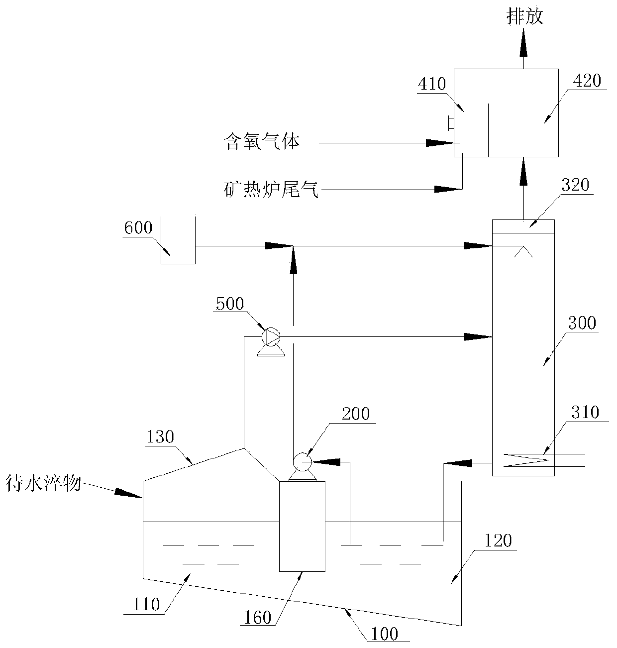
[0054] Compared with Example 1, the difference between the three-phase separation device for water-quenched products and the water-quenched flue gas treatment system of this embodiment is: figure 2 As shown, it also includes an air supply mechanism for replenishing the water quenching tank 110 when the output of the water quenching flue gas is lower than the preset value; 140 and a one-way breathing valve 150 disposed on the air hole 140 .

[0055] The method of adopting the water-quenching flue gas treatment system of embodiment 1 or embodiment 2 can treat the water-quenching flue gas in an efficient, energy-saving and environment-friendly manner, and the treated water-quenching flue gas can be discharged directly.


PUM


Abstract

The invention discloses a three-phase separation device for a water quenching product and a water quenching flue gas treatment system and method. The three-phase separation device for a water quenching product comprises a reaction tank, a partition wall extending below the liquid level is arranged in the reaction tank, and the partition wall divides the reaction tank into a water quenching tank and a sediment tank which are connected through a flowing channel below the partition wall. A water quenching object is converted into water quenching flue gas and water quenching slag after entering the water quenching tank, the water quenching slag flows into the sediment tank through the flowing channel, and a gas collecting hood for collecting the water quenching flue gas is arranged above the water quenching tank. The upper parts of the water quenching tank and the sediment tank are separated, so that water quenching flue gas generated by the water quenching tank can be collected by the gascollecting hood in a more centralized manner. The water quenching tank is communicated with the lower part of the sediment tank, so that the temperature of the water quenching slag can be fully reduced in the process of flowing to the sediment tank, and the liquid in the sediment tank and the liquid in the water quenching tank can be subjected to heat transfer, thereby reducing the temperature ofthe liquid in the water quenching tank and improving the water quenching efficiency.

Description

technical field [0001] The invention relates to the technical field of water quenching, in particular to a three-phase separation device for water quenching products and a water quenching flue gas treatment system and method. Background technique [0002] Using water as the quenching agent can make the liquid high-temperature slag be rapidly cooled and split into small particles of water-quenched slag, which can be directly used as building materials without crushing. However, a large amount of water-quenched flue gas with high temperature and high pressure characteristics will be produced during the water quenching process. On the one hand, if these water-quenched flue gases are not properly handled in time, there will be explosion hazards. On the other hand, the collected water-quenched flue gas There is no efficient and energy-saving treatment technology for the resulting environmental problems. Contents of the invention [0003] The first technical problem to be solve...

Claims


Application Information

Patent Timeline
IPC IPC(8): B01D47/06B01D53/26
CPCB01D47/06B01D53/26B01D2247/10B01D2257/80B01D2258/0283
Inventor 高麟吴志强
Owner CHENGDU INTERMENT TECH
Why Eureka
Try Eureka