Reaction type crushing device for coal mine

An impact crushing and coal mine technology, applied in grain processing and other directions, can solve the problems that the distance between the blow hammer and the impact plate cannot be adjusted, and the relative distance and inclination cannot be adjusted at the same time, so as to improve the applicability.

Active Publication Date: 2020-05-15
张其朋
View PDF13 Cites 5 Cited by
  • Summary
  • Abstract
  • Description
  • Claims
  • Application Information

AI Technical Summary

Problems solved by technology

[0003] However, the distance between the blow bar and the impact plate of the existing impact crusher cannot be adjusted. After the impact crusher leaves the factory, the distance between the blow bar and the impact plate of the impact device is fixed. Hinged connection, the other end of the impact plate is adjusted through the adjustment device, which can only realize the change of the inclination angle between the impact plate and the blow bar, but cannot realize the adjustment of the relative distance and the degree of inclination at the same time; according to actual production experience, different sizes The crushing efficiency of coal mines is different when the distance between the blow bar and the impact plate is different. When the distance between the blow bar and the impact plate is too large, large coal mines will pass through before the particle size is broken enough to meet the requirements. The discharge port at the lower end discharges

Method used


Image

  • Reaction type crushing device for coal mine
  • Reaction type crushing device for coal mine
  • Reaction type crushing device for coal mine

Examples


Embodiment 1

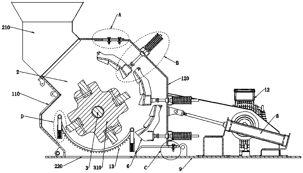
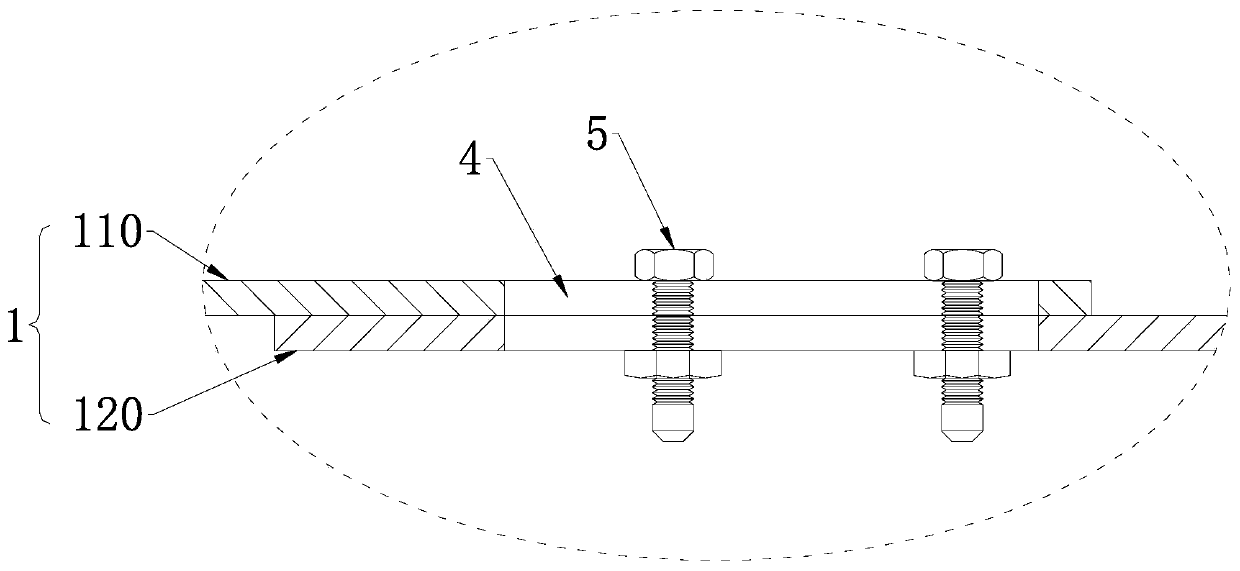
[0039] The impact crushing device for coal mines of the present invention includes a shell body 1, the upper end of the shell body 1 is provided with a feed port 210, the lower end of the shell body 1 is provided with a discharge port 220, and the shell body 1 includes a first shell Body 110 and second housing 120, one side of the first housing 110 is open, the second housing 120 blocks the opening of the first housing 110, the first housing 110 overlaps with the second housing 120, The first shell 110 and the second shell 120 are overlapped by a guide groove 4, and the guide groove 4 is equipped with a fixing assembly 5. The first shell 110 and the second shell 120 are buckled together to form a crushing chamber 2. A rotor 3 is installed in the cavity 2, and the rotor 3 is set with a blow bar 310. One end of the rotor 3 is connected to the first housing 110 in rotation, and the other end of the rotor 3 penetrates the outer wall of the first housing 110 and is connected with a ...

Embodiment 2

[0042] This embodiment is further optimized on the basis of Embodiment 1 as follows: the upper end and the front and rear ends of the second housing 120 are overlapped with the first housing 110, and the second housing 120 is overlapped with the first housing 110. A plurality of guide grooves 4 are arranged at the joints, and a fixing component 5 is arranged in any guide groove 4 .

[0043] After adopting the above technical solution: the upper end and the front and rear ends of the second housing 120 are provided with side plates, when the second housing 120 is installed with the first housing 110, the upper end and the front and rear ends of the second housing 120 are both It is overlapped with the first housing 110, and the overlapped part is quickly fixed and disassembled by the fixing assembly 5 and the guide groove 4, so as to realize stepless adjustment; as an idea, multiple guide grooves 4 can be arranged at intervals, and each guide groove 4 A plurality of fixing comp...

Embodiment 3

[0045] This embodiment is further optimized on the basis of Embodiment 1 as follows: the lower end of the housing body 1 is provided with a placement plate 9, the placement plate 9 is provided with an opening aligned with the discharge port 220, and the lower end of the second housing 120 Bending to the side away from the crushing chamber 2 to form a positioning plate 11, a support plate 10 is provided between the placement plate 9 and the positioning plate 11, and a guide groove 4 is also opened through the support plate 10 and the positioning plate 11, and the guide groove 4 is also provided There are fixed components 5. The guide groove 4 is a waist-shaped groove, and the fixing assembly 5 is a bolt assembly.

[0046] After adopting the above technical solution: the lower end of the second housing 120 is bent outward to form a positioning plate 11, and the positioning plate 11 and the support plate 10 are also fixed by the cooperation of the fixing assembly 5 and the guide ...


PUM


Abstract

The invention discloses a reaction type crushing device for coal mine, and relates to the technical field of coal mine crushing devices. The reaction type crushing device can regulate spacing betweena reaction plate and a plate hammer according to a practical use condition while regulating a relative distance and relative inclination degree between the plate hammer and a reaction plate of a reaction device, and guarantees that coal mines discharged from a position between the plate hammer and the reaction plate can meet required particle diameters. A first housing is in lap joint to a secondhousing; the first housing and the second housing are locked to form a crushing cavity; a rotor is arranged in the crushing cavity; the rotor is sleeved by the plate hammer; one end of the rotor is rotatably connected to the first housing, and the other end of the rotor penetrates through the outer wall of the first housing, and then is connected to a drive device; the reaction plate at the outerside of the plate hammer is further arranged in the crushing cavity; the reaction plate is connected to a regulating device which penetrates through the outer wall of the second housing; and a supporting device is further arranged on the outer wall of the second housing.

Description

technical field [0001] The invention relates to the technical field of coal mine crushing devices, in particular to an impact crushing device for coal mines. Background technique [0002] It is an area where humans mine coal resources in coal-rich mining areas, generally divided into underground coal mines and open-pit coal mines. When the coal seam is far away from the surface, it is generally selected to excavate the coal by digging the roadway underground, which is an underground coal mine. When the distance between the coal seam and the surface is very short, it is generally chosen to directly strip the surface soil layer to excavate coal, which is an open-pit coal mine. The vast majority of coal mines in my country are underground coal mines. Regardless of underground coal mines and open-pit coal mines, they are often very large during mining, so large pieces of coal mines will be crushed for the convenience of transportation. As a commonly used crushing machine, the...

Claims


Application Information

Patent Timeline
IPC IPC(8): B02C13/09B02C13/282B02C13/28B02C13/26B02C13/284B02C13/30B02C13/31
CPCB02C13/09B02C13/26B02C13/2804B02C13/282B02C13/284B02C13/30B02C13/31
Inventor 张其朋王英杰杨壮张泽锐黄洁
Owner 张其朋
Why Eureka
Try Eureka