Intelligent punching device for case

A punching device and chassis technology, which is applied in the field of mechanical processing, can solve the problems of insufficient punching accuracy, reduce the service life of the punch, affect the punching of the punch, etc., and achieve the effect of improving the effect, reducing the amount of deformation, and increasing the accuracy

Active Publication Date: 2020-05-15
HANGZHOU FENGHENG ELECTROMECHANICAL
View PDF8 Cites 10 Cited by
  • Summary
  • Abstract
  • Description
  • Claims
  • Application Information

AI Technical Summary

Problems solved by technology

[0003] When the existing punching machine is used for punching, because the punch is used to press the punch down on the chassis plate to punch out the hole pattern, according to the force of the punching part, the inside of the punched hole is all collapsed downwards, In this way, it is ok for low-requirement chassis, but it cannot be used for some high-precision requirements, and the bottom surface will collapse to form edges and corners, which will also cause scratches to machinery or users.
[0004] The inner wall of the punched hole of the chassis plate is rough, with a lot of burrs and sharp ends, which is not high enough for the processed chassis plate, and these burrs will rub the punch, causing less scratches on the cutting edge of the punch The service life of the punch is shortened, and the sliding of the punch will also bring burrs. The burr adhered to the punch will affect the subsequent punching of the punch, so that the stamping shape of the punch is changed due to the influence of the adhered burr during punching. Insufficient punching accuracy

Method used


Image

  • Intelligent punching device for case
  • Intelligent punching device for case
  • Intelligent punching device for case

Examples


Embodiment Construction

[0024] The following will clearly and completely describe the technical solutions in the embodiments of the present invention with reference to the accompanying drawings in the embodiments of the present invention. Obviously, the described embodiments are only some, not all, embodiments of the present invention. Based on the embodiments of the present invention, all other embodiments obtained by persons of ordinary skill in the art without making creative efforts belong to the protection scope of the present invention.

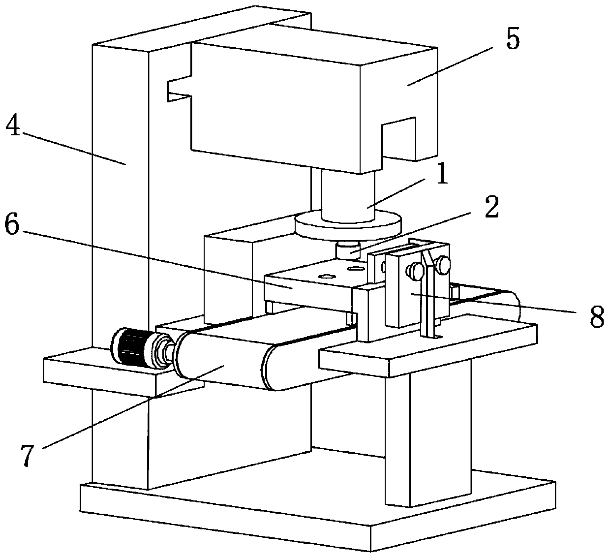
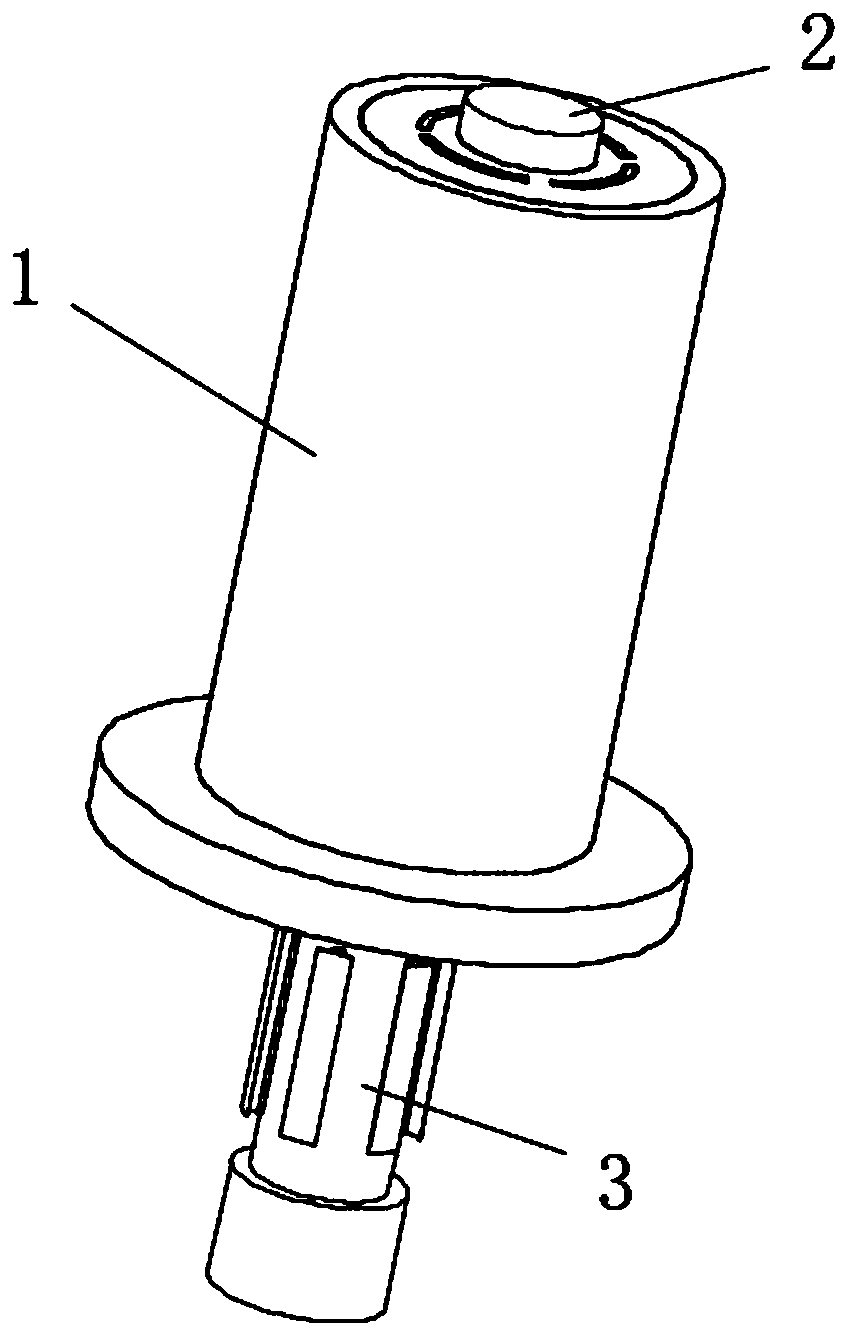
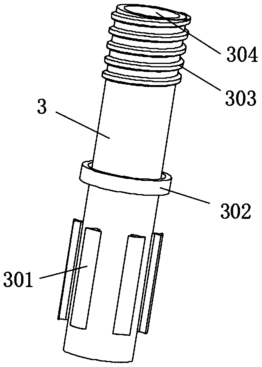
[0025] see Figure 1-7 , a casing intelligent processing punching device, including a body, the top of the body is provided with a control and adjustment device, the middle of the body is provided with a cleaning belt, the top of the cleaning belt is provided with a mold, and the front of the mold is provided with a clamping and positioning device, The bottom of the control adjustment device is connected with a stamping jacket and a punch structure, and the ou...


PUM


Abstract

The invention relates to the technical field of machining and discloses an intelligent punching device for a case. The intelligent punching device for the case comprises a body, wherein a control regulation device is arranged on the top of the body, a material clearing strip is arranged in the middle of the body, a die is arranged above the material clearing strip, a clamping and positioning device is arranged on the front surface of the die, the bottom of the control regulation device is connected to a punching outer sleeve and a punch structure, a punching sleeve structure is connected outside the punch structure in a sleeving manner, and a scraper, a reverse punch and a spiral convex ring are successively arranged from bottom to top of the outer surface of the punching sleeve structure.The intelligent punching device for the case can correct a collapsed hole edge during punching by arranging the punching outer sleeve pressing the surface of a panel of the case and the reverse punchcapable of punching reversely during punching, and can remove burrs attached to the inner wall of the a punched hole by arranging the punching sleeve structure provided with the reverse punch, the scraper and the spiral convex ring, so that the punching precision is improved.

Description

technical field [0001] The invention relates to the technical field of mechanical processing, in particular to an intelligent processing punching device for a chassis. Background technique [0002] At present, the case is very useful and needs to be used in many places, and punching is a very important step in the processing of the case. The quality of punching is directly related to the use of the subsequent case, so now the requirements for punching are also Higher and higher. [0003] When the existing punching machine is used for punching, because the punch is used to press the punch down on the chassis plate to punch out the hole pattern, according to the force of the punching part, the inside of the punched hole is all collapsed downwards, In this way, it is ok for low-requirement chassis, but it cannot be used for some high-precision requirements, and the bottom surface will collapse to form edges and corners, which will also cause scratches to machinery or users. ...

Claims


Application Information

Patent Timeline
Patent Type & Authority Applications(China)
IPC IPC(8): B21D28/34B21D28/26B21D19/00B21D43/00
CPCB21D19/005B21D28/26B21D28/34B21D43/003
Inventor 孔磊
Owner HANGZHOU FENGHENG ELECTROMECHANICAL
Why Eureka
Try Eureka