Chamfering tool for grooving machine frame sliding block

A technology of slotting machine and frame, which is applied in the direction of grinding frame, manufacturing tool, grinding slide plate, etc. It can solve the problem of affecting processing accuracy, offset of slider chamfering processing, poor clamping and limiting effect of slider, etc. problem, to achieve the effect of convenient processing and positioning

Active Publication Date: 2020-05-15
JIANGSU HAIRUI CNC MACHINE TOOL CO LTD
View PDF7 Cites 2 Cited by
  • Summary
  • Abstract
  • Description
  • Claims
  • Application Information

AI Technical Summary

Problems solved by technology

[0004] When chamfering the existing rack slider, it is positioned by tooling. Since the slider is generally a cuboid, when performing end chamfering, it is necessary to change the position of the slider to grind different edges and corners, and it is inconvenient to control after the position is changed. The amount of chamfering for each corner is exactly the same; at the same time, the existing positioning tooling has a poor clamping and limiting effect on the slider, which may easily cause the slider to shift during chamfering and affect the machining accuracy

Method used


Image

  • Chamfering tool for grooving machine frame sliding block
  • Chamfering tool for grooving machine frame sliding block
  • Chamfering tool for grooving machine frame sliding block

Examples


Embodiment Construction

[0028] The following will clearly and completely describe the technical solutions in the embodiments of the present invention with reference to the accompanying drawings in the embodiments of the present invention. Obviously, the described embodiments are only some, not all, embodiments of the present invention. Based on the embodiments of the present invention, all other embodiments obtained by persons of ordinary skill in the art without making creative efforts belong to the protection scope of the present invention.

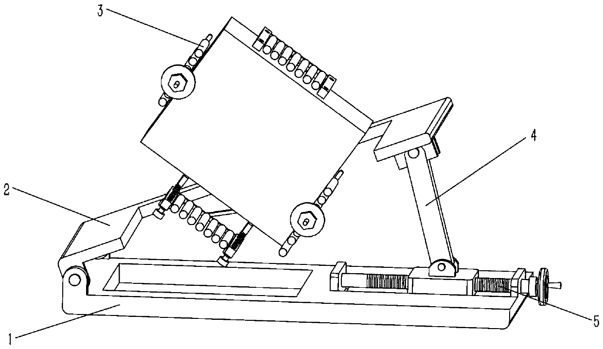
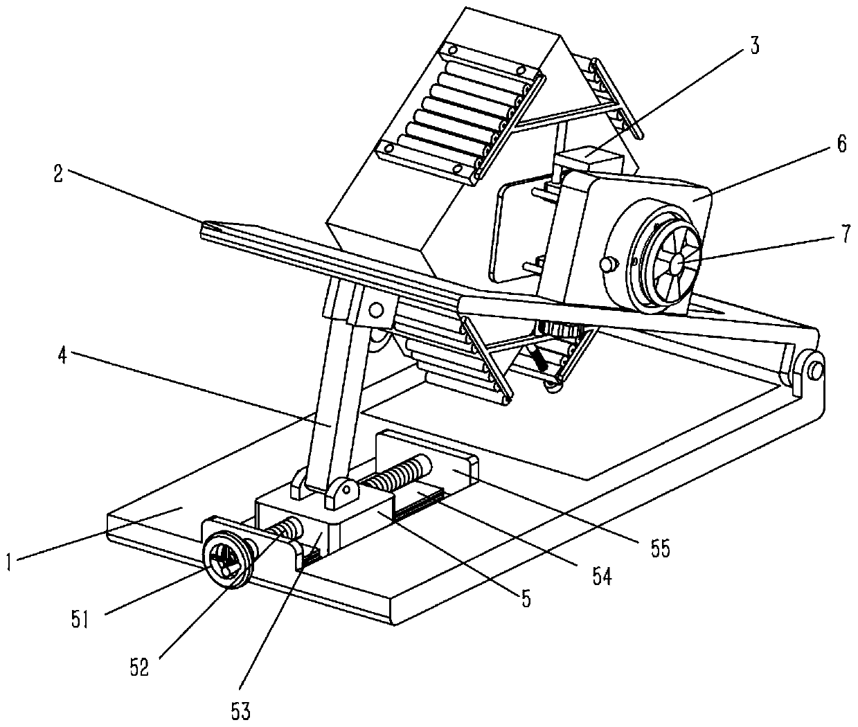
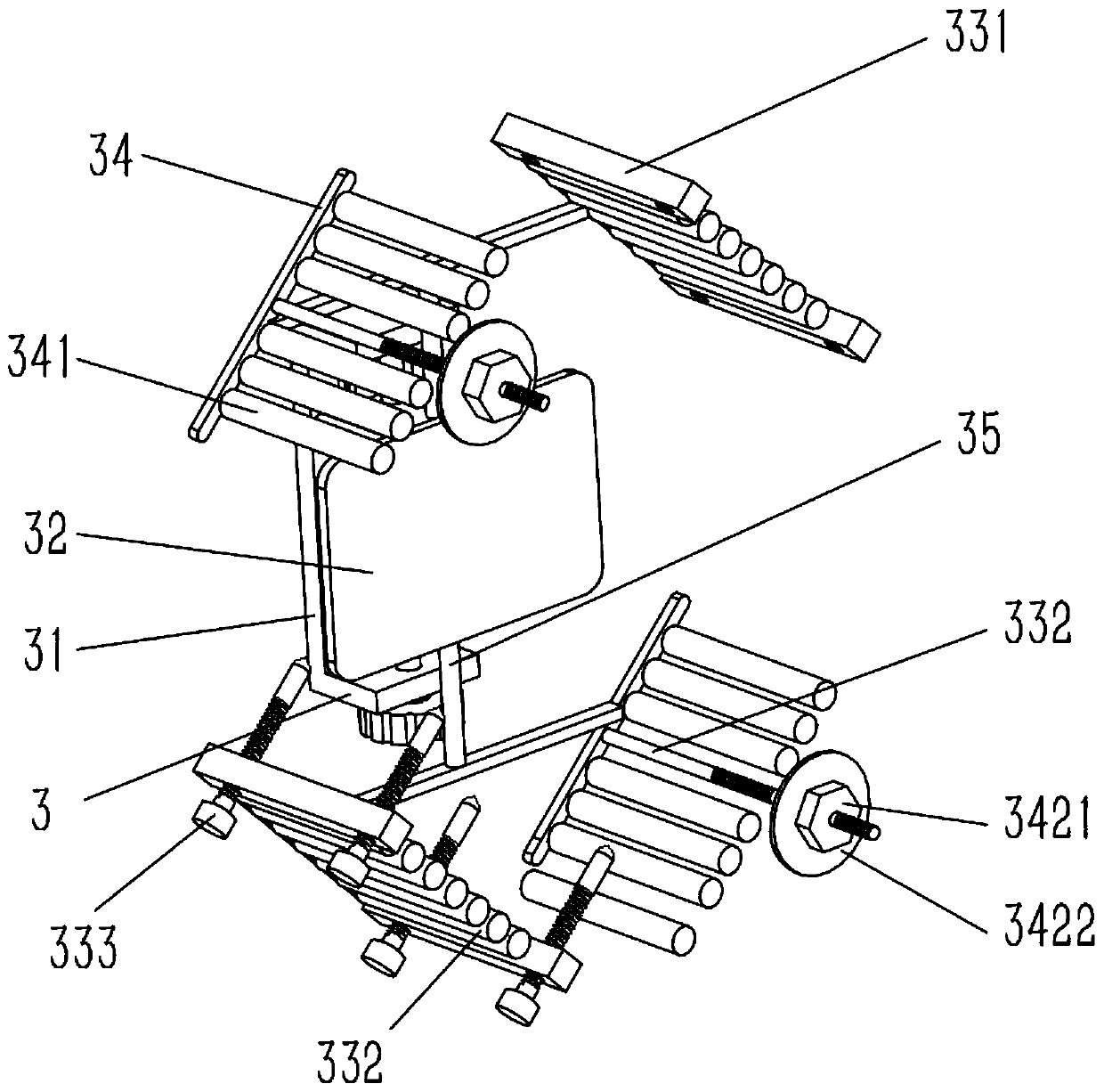
[0029] see Figure 1-8 , the present invention provides a technical solution: a chamfering tool for a slotting machine frame slider, including a base plate 1, one end of the base plate 1 is connected with a positioning plate 2, and the bottom of the positioning plate 2 away from the end of the base plate 1 is hinged with a support rod 4 , the bottom of the support rod 4 is connected with an angle adjustment mechanism 5, the top side of the positioning plate 2 ...


PUM


Abstract

The invention discloses a chamfering tool for a grooving machine frame sliding block. The tool comprises a bottom plate, a positioning plate is hinged to one end of the bottom plate, a supporting rodis hinged to the bottom of the end, away from the bottom plate, of the positioning plate, an angle adjusting mechanism is connected to the bottom of the supporting rod, a supporting plate is fixed toone side of the top of the positioning plate, a rotating shaft is rotationally connected to the center of the supporting plate, the two ends of the rotating shaft penetrate through the two sides of the supporting plate correspondingly, and a center positioning device and a rotating mechanism are fixed to the two ends of the rotating shaft; and the center positioning device comprises a U-shaped base, the rotating shaft is fixed to the center of the U-shaped base, a first sliding rail is fixed to the U-shaped base, a first adjusting screw rod is rotationally connected to the inner walls of the upper side and the lower side of the U-shaped base, and one end of the first adjusting screw rod penetrate through the outer wall of the U-shaped base to be provided with an adjusting knob. The tool has the characteristics that positioning is convenient, chamferings of the corner angles of the sliding block can be conveniently controlled be to be the same, and the machining angle can be conveniently adjusted.

Description

technical field [0001] The invention relates to the technical field of chamfering processing, in particular to a chamfering tool for a slider of a slotting machine frame. Background technique [0002] Chamfering refers to the processing form of cutting the corners of the workpiece into a certain slope. The purpose of chamfering parts is to remove the burrs on the parts due to machining, and to facilitate the assembly of parts, chamfers are generally made at the ends of parts. [0003] The slotting machine is a kind of equipment used for slotting the workpiece. When the slotting machine performs slotting work, the up and down movement of the tool depends on the cooperation of the slider and the slide rail in the slotting machine frame, and the slotting machine frame slides As an important part of the slotting machine, the block is installed in the rack slide rail, and the rack slide block needs to be chamfered before installation. [0004] When chamfering the existing rack ...

Claims


Application Information

Patent Timeline
Patent Type & Authority Applications(China)
IPC IPC(8): B24B9/00B24B41/02B24B41/06B24B55/00
CPCB24B9/00B24B41/02B24B41/06B24B55/00
Inventor 张达水
Owner JIANGSU HAIRUI CNC MACHINE TOOL CO LTD
Why Eureka
Try Eureka