Hydrofoil device and hydrofoil ship

A hydrofoil and hydrofoil technology, applied in the direction of ship hull, ship construction, hull design, etc., can solve the problems of increasing wing resistance, reducing hydrofoil lifting resistance, small lift, etc., to achieve the effect of increasing speed

Active Publication Date: 2020-05-15
符海玉
View PDF16 Cites 1 Cited by
  • Summary
  • Abstract
  • Description
  • Claims
  • Application Information

AI Technical Summary

Problems solved by technology

The wings of the hydrofoil boat and the hull are fixedly connected, and the speed of the boat and the hydrofoil relative to the water is the same. When the speed of the hydrofoil relative to the water is high when the ship sails at high speed, there is still greater resistance and consumes more energy.
[0003] In addition, when the hydrofoil sails, the water gives the hydrofoil backward resistance, which also consumes more energy
[0004] When the existing hydrofoil boat accelerates above a certain speed when sailing at high speed, the speed of the hydrofoil relative to the water is the same as the speed of the ship. If the speed of the hydrofoil relative to the water is too large, a large number of cavitation will be generated, which will lead to the damage of the hydrofoil. Reduced lift drag and instability so that the speed of the hydrofoil cannot be increased further
[0005] The hydrofoils of existing hydrofoil boats are mostly one main wing or two main wings, and the lift provided by the hydrofoils is small. If more wings are used, there will be interference between the wings, which will greatly increase the drag of the wings and reduce the lift of the wings. lift

Method used


Image

  • Hydrofoil device and hydrofoil ship
  • Hydrofoil device and hydrofoil ship
  • Hydrofoil device and hydrofoil ship

Examples


Embodiment 1

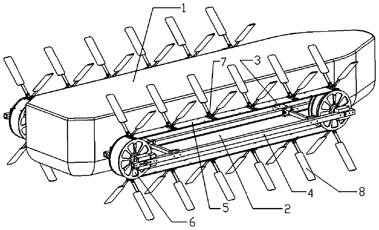
[0056] like figure 1 Shown is a schematic diagram of a first embodiment of the present invention.

[0057] It includes a hull 1, an annular motion device 2, and a connector 3. The connector 3 connects the annular motion device 2 and the hull 1 together. The number of the annular motion devices 2 is two. side.

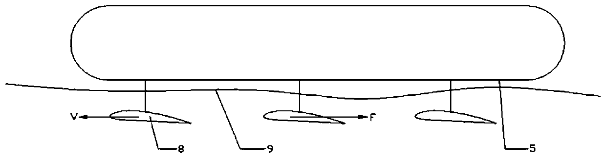
[0058]Each annular motion device 2 includes a hydrofoil device frame 4 , a conveyor belt 5 , a runner 6 , a driving device, a hydrofoil fixing member 7 , and a hydrofoil 8 , and the hydrofoil fixing member 7 fixes a pair of hydrofoils on the conveyor belt 5 . When the driving device drives the runner to rotate, it drives the conveyor belt 5 to move, and the hydrofoil 8 fixed on the conveyor belt 5 circulates together with the conveyor belt 5. The cyclic movement speed is greater than the speed of the boat, and the hydrofoil pushes the water backward to provide the ship's forward movement. Power, with the gradual increase in the speed of the conveyor belt circulatory m...

Embodiment 2

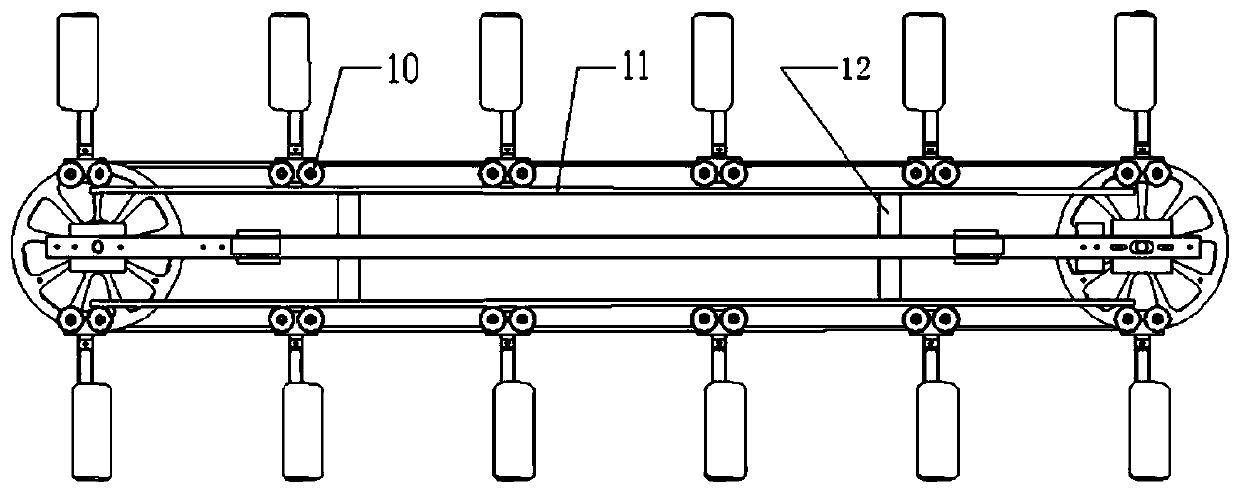
[0062] The annular motion device of the second embodiment is as follows: image 3 As shown, in order not to move too much vertically upward against the conveyor belt when the hydrofoil provides greater lift, the roller 10 is installed on the hydrofoil fixing part, the track 11 is installed on the hydrofoil device frame, the track 11 and the hydrofoil device The racks 4 are fixed together by the track connectors 12, so that the lift force of the hydrofoil acts on the track through the rollers, thereby restricting the upward or downward movement of the hydrofoil and ensuring the stability of the hydrofoil operation.

Embodiment 3

[0064] The third example is Figure 5 As shown in the figure, the number of annular motion devices in this embodiment is four, and each of the four annular motion devices has a set of power systems to adjust the balance of the ship through different speeds; The speed is different, adjust the left and right balance of the boat.

[0065] As other embodiments of the present invention, the annular motion device of the present invention is not limited to a conveyor belt device; it can be a chain, a sprocket device, wings or wing struts are fixed on the chain, and make a circular motion together with the chain; it can also be a wire rope, a wire rope Wheel device, wings or wing struts are fixed on the wire rope, and make circular motion with the wire rope; it can also be a circular linear motor device. like Image 6 The annular track 13 is shown as a stator, and a plurality of rotors 14 are arranged around the annular track. The rotors 14 and the coils 15 are fixed together.

[0...


PUM


Abstract

The invention discloses a hydrofoil device and a hydrofoil ship. The hydrofoil device comprises an annular motion device and a plurality of hydrofoils arranged on the annular motion device. The annular motion device can perform active or passive annular circulating motion; and the hydrofoils can circularly move along with the annular movement device. According to the hydrofoil device and the hydrofoil ship, the resistance of the hydrofoil ship during sailing can be reduced, the wing sailing speed of the hydrofoil ship is increased, and inter-wing adverse interference generated when multiple wings are installed on the hydrofoil ship is weakened.

Description

technical field [0001] The present invention relates to a water vehicle, and more particularly, to a hydrofoil device and a hydrofoil boat. Background technique [0002] A hydrofoil is a high-speed boat. There are brackets on the bottom of the hull, and hydrofoils are installed. When the speed of the boat is gradually increased, the buoyancy provided by the hydrofoils will lift the hull out of the water (called hydrofoil sailing or hydrofoil sailing), which can effectively reduce the resistance of the water and at the same time increase the sailing speed. The wings and the hull of the hydrofoil ship are fixedly connected, and the speed of the ship and the hydrofoil relative to the water is the same. When the ship sails at high speed, the speed of the hydrofoil relative to the water is large, and there is still a large resistance, which will consume more energy. . [0003] In addition, when the hydrofoil sails, the water provides the hydrofoil with backward resistance, whi...

Claims


Application Information

Patent Timeline
Patent Type & Authority Applications(China)
IPC IPC(8): B63B1/26B63B1/28B63B1/40B63B1/18
CPCB63B1/26B63B1/28B63B1/40B63B1/18B63B2001/186Y02T70/10
Inventor 符海玉符海娇
Owner 符海玉
Why Eureka
Try Eureka