An EMC Design Method for UAV Steering Gear Control Drive System

A drive system, electromagnetic compatibility technology, applied in aircraft transmission, aircraft power transmission, aircraft power devices and other directions, can solve problems such as uncontrolled crashes, electromagnetic interference, and short battery life of fixed-wing UAVs

Active Publication Date: 2021-03-16
洛阳安怀达智能科技有限公司
View PDF16 Cites 0 Cited by
  • Summary
  • Abstract
  • Description
  • Claims
  • Application Information

AI Technical Summary

Problems solved by technology

[0002] Most of the existing civilian UAVs are multi-rotor structures. The mechanical structure of multi-rotor UAVs is simple, and the control is relatively easy, but they have the disadvantages of slow speed, small carrying capacity, and short endurance time. The civil field with carrying capacity and long-term battery life is not competent; and for fixed-wing UAVs, its flight attitude control is realized through the actions of the wing ailerons, vertical tails, and elevating tails, while the wing ailerons, vertical tails, The movement of the elevating tail needs to be controlled by the steering gear, so the UAV steering gear control drive system is a key subsystem of the fixed-wing UAV, but because of its high development difficulty, there is currently no fixed-wing UAV steering gear on the market. Control-driven commercial products, thus affecting the development of civilian fixed-wing UAV products
[0003] In addition, civilian fixed-wing UAVs will be equipped with electronic equipment such as optoelectronics and radars during use, so they have the characteristics of a complex electromagnetic environment. If the EMC design of the UAV steering gear control drive system is poor, it is easy to cause UAVs Electromagnetic interference is generated between the steering gear control drive system and the electronic equipment such as optoelectronics, radar, and communication equipment, which affects the normal flight control of the fixed-wing UAV. In severe cases, it may even cause the fixed-wing UAV to crash out of control. The electromagnetic compatibility design of the UAV steering gear control drive system is one of the necessary design tasks to ensure that the UAV steering gear control drive system works reliably and stably in complex electromagnetic environments; at the same time, the UAV steering gear control drive system As an independently sold subsystem, the system itself should have a low level of electromagnetic radiation in order to achieve good electromagnetic compatibility with other systems of the customer; systematic revelation

Method used


Image

  • An EMC Design Method for UAV Steering Gear Control Drive System
  • An EMC Design Method for UAV Steering Gear Control Drive System

Examples


Embodiment Construction

[0034] The present invention can be explained in detail through the following examples, and the purpose of disclosing the present invention is to protect all technical improvements within the scope of the present invention.

[0035] An electromagnetic compatibility design method for an unmanned aerial vehicle steering gear control drive system, the electromagnetic compatibility design process is synchronized with the development process of the unmanned aerial vehicle steering gear control drive system, specifically comprising the following steps:

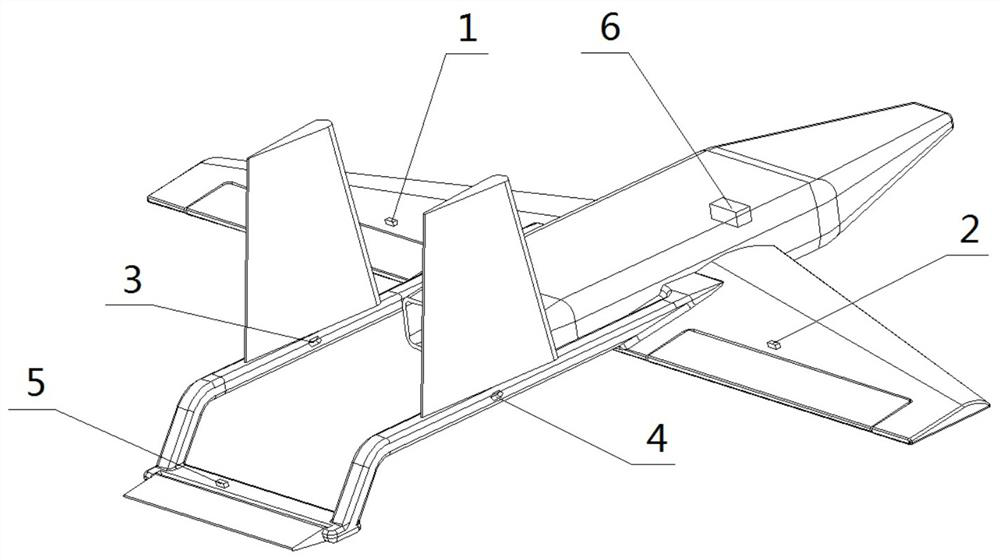
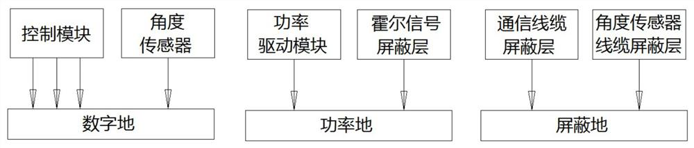
[0036] S1. Analysis and determination of interference sources: UAV servo control drive system includes control module, power drive module, and rudder actuator; the control module includes DSP, CAN communication interface circuit, bus driver, angle decoding circuit, and differential receiving circuit; Wherein the power drive module includes a logic synthesis circuit, an overcurrent protection circuit, a drive circuit, and an inverter ...


PUM


Abstract

An electromagnetic compatibility design method for an unmanned aerial vehicle steering engine control driving system is synchronous with development and verification processes of an unmanned aerial vehicle steering engine control driving system, and comprises interference source analysis and determination, sensitive circuit analysis and determination, electromagnetic compatibility scheme design and software anti-interference design, wherein the electromagnetic compatibility scheme design is the key point of the electromagnetic compatibility design of the unmanned aerial vehicle steering enginecontrol driving system, and comprises the overall layout design of the control driving system, the grounding design, the isolation design, the PCB wiring and grounding design, the electromagnetic shielding design and the connecting cable shielding design. The unmanned aerial vehicle steering engine control driving system designed and verified through the method has the extremely low electromagnetic radiation level and the extremely high electromagnetic interference resistance, meanwhile, the stable and reliable working capacity in the complex electromagnetic environment is guaranteed, and therefore good electromagnetic compatibility is achieved.

Description

technical field [0001] The invention relates to the technical field of design of an unmanned aerial vehicle steering gear control drive system, in particular to an electromagnetic compatibility design method for the unmanned aerial vehicle steering gear control drive system. Background technique [0002] Most of the existing civilian UAVs are multi-rotor structures. The mechanical structure of multi-rotor UAVs is simple, and the control is relatively easy, but they have the disadvantages of slow speed, small carrying capacity, and short endurance time. The civil field with carrying capacity and long-term battery life is not competent; and for fixed-wing UAVs, its flight attitude control is realized through the actions of the wing ailerons, vertical tails, and elevating tails, while the wing ailerons, vertical tails, The movement of the elevating tail needs to be controlled by the steering gear, so the UAV steering gear control drive system is a key subsystem of the fixed-win...

Claims


Application Information

Patent Timeline
Patent Type & Authority Patents(China)
IPC IPC(8): B64F5/00B64C13/38
CPCB64C13/38B64F5/00
Inventor 向华安张占良焦郑瑞王浩李艳丽
Owner 洛阳安怀达智能科技有限公司
Why Eureka
Try Eureka