Sliding lifting device and method for arc decorative plate of building steel structure bridge

A technology of decorative panels and construction steel, applied in portable lifting devices, bridges, buildings, etc., can solve problems such as the influence of operation difficulty, limit the feasibility of bridge construction, and limit the construction environment, so as to avoid the limitation of operation difficulty and improve the application Performance and practicability, and the effect of ensuring installation efficiency

Pending Publication Date: 2020-05-15
上海川勤建筑工程有限公司
View PDF4 Cites 0 Cited by
  • Summary
  • Abstract
  • Description
  • Claims
  • Application Information

AI Technical Summary

Problems solved by technology

[0003] 1. For the construction of decorative panels of traditional steel structure bridges, large-scale hoisting and hoisting machinery are usually installed at the bottom of the bridge, or traction machinery is installed on the bridge surface, and methods such as manual hoisting and engineering devices are used for construction. The on-site construction is mostly affected by the bridge The strength of the foundation, the limitation of the fragile riverbed and the limitation of the narrow road at the lower end of the bridge make it impossible to apply large-scale hoisting machinery. At the same time, the construction at the bridge deck end is also easily affected by the weight of the structure to be installed, such as decorative panels, and the hoisting height, which ma

Method used


Image

  • Sliding lifting device and method for arc decorative plate of building steel structure bridge
  • Sliding lifting device and method for arc decorative plate of building steel structure bridge
  • Sliding lifting device and method for arc decorative plate of building steel structure bridge

Examples


Example Embodiment

[0032] The specific implementation of the invention will be further described below in conjunction with the drawings.

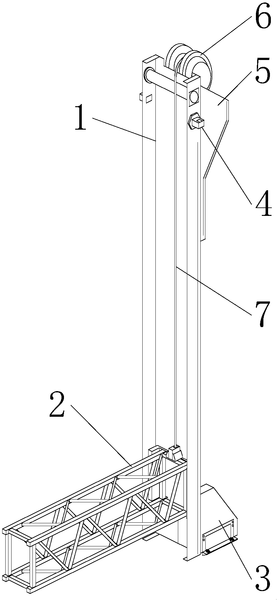
[0033] Such as figure 1 As shown, the sliding lifting device of the arc-shaped decorative panel of the steel structure bridge of the present invention includes a steel rail structure, a bracket structure and a sliding system.

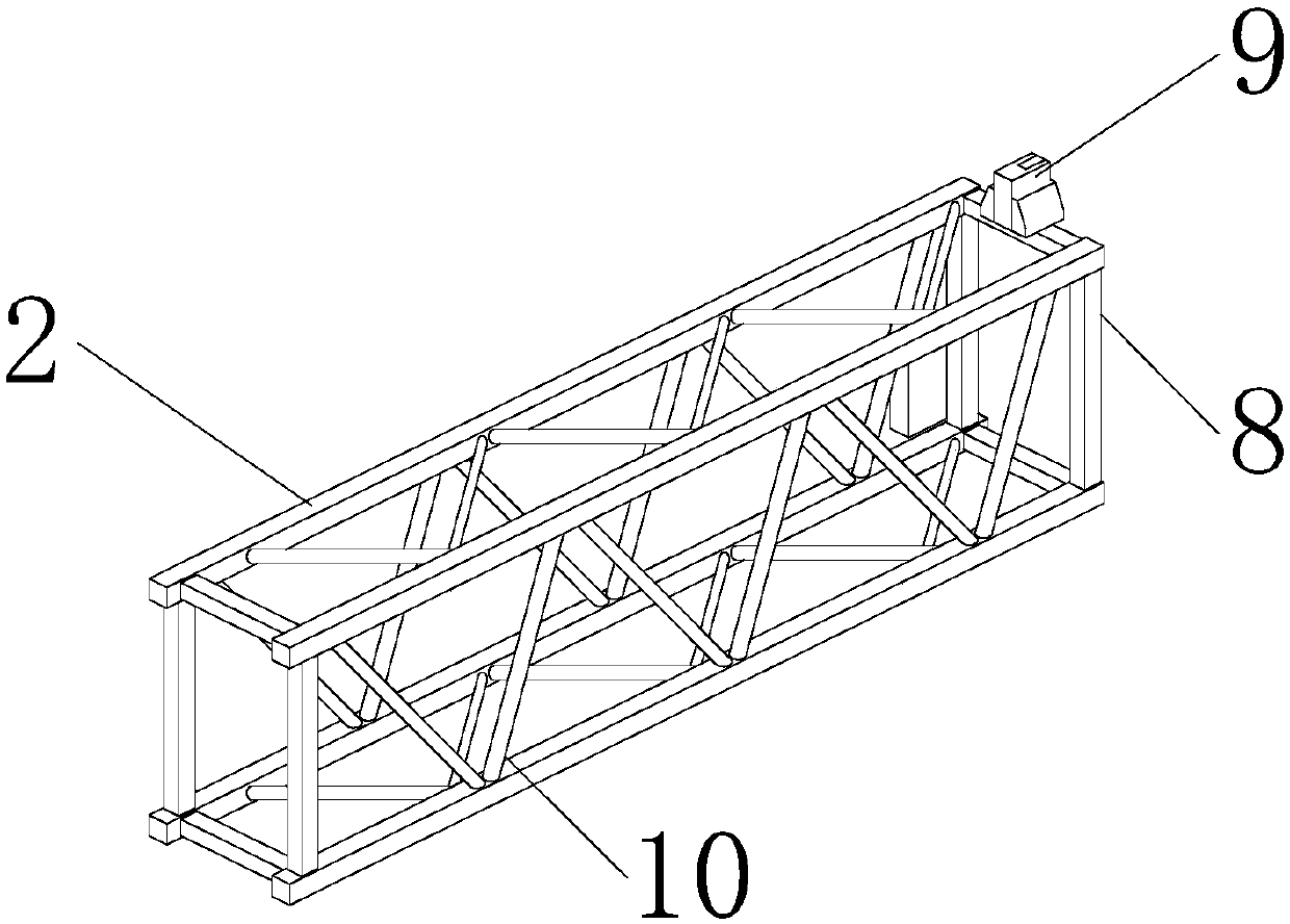
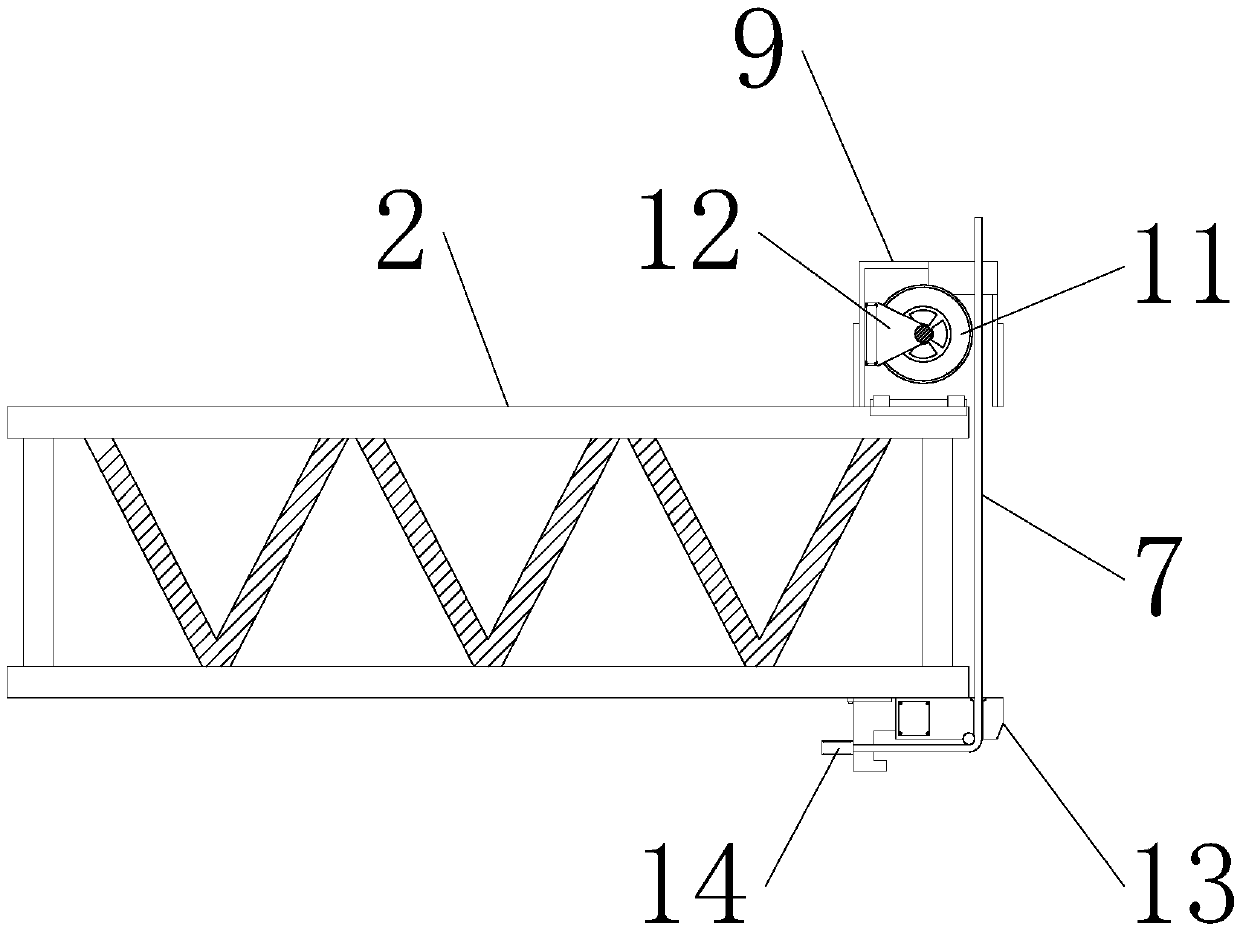
[0034] Such as Figure 1-6 As shown, the rail structure includes a main steel frame 1, a steel frame base 3, a back groove frame 5, and a sliding plate 23; the main steel frame 1 is a concave channel steel frame, and the upper and lower ends of the main steel frame 1 are both penetrated for assembly Expansion bolts, sliding plate 23 is embedded in the front of the main steel frame 1, two welding plates 29 are symmetrically arranged on the front of the sliding plate 23, the surface of the welding plate 29 is slotted with strip screw holes, and the inner middle of the sliding plate 23 is opened The slot is provided with a stranding groove 28,...


PUM


Abstract

The invention discloses a sliding lifting device and method for an arc decorative plate of a building steel structure bridge, and belongs to the technical field of engineering construction. Each steelrail structure comprises a main steel frame, a steel frame base, a back groove frame and a sliding plate, wherein the main steel frame is a concave channel steel frame; expansion bolts for assembly are arranged at the upper end and the lower end of the main steel frame in a penetrating mode; the sliding plate is embedded on the front face of the main steel frame; two welding plates are symmetrically arranged on the front face of the sliding plate; strip-shaped screw hole grooves are formed in the surfaces of the welding plates; and a twisted wire groove is formed in the middle of the inner side of the sliding plate. According to the device and the method, the steel rail structures matched with the steel structure bridge are utilized, then the initial installation of the sliding lifting device is convenient, meanwhile, the structure strength of the steel structure bridge is utilized to laterally reinforce the structure of the device, and then the stability of the structure during construction is guaranteed; and meanwhile, a bracket structure is light and stable, the arc decorative plate required to be installed is convenient to carry, and a sliding system is utilized to carry out longitudinal sliding lifting, so that the construction process is stable and reliable, the safety is high, and the applicability of the device is improved to a certain extent.

Description

technical field [0001] The invention relates to the technical field of engineering construction, in particular to a sliding lifting device and method for a curved decorative plate of a building steel structure bridge. Background technique [0002] When the traditional slip lifting device and method are applied to the construction of steel structure bridges, there are the following deficiencies: [0003] 1. For the construction of decorative panels of traditional steel structure bridges, large-scale hoisting and hoisting machinery are usually installed at the bottom of the bridge, or traction machinery is installed on the bridge surface, and methods such as manual hoisting and engineering devices are used for construction. The on-site construction is mostly affected by the bridge The strength of the foundation, the limitation of the fragile riverbed and the limitation of the narrow road at the lower end of the bridge make it impossible to apply large-scale hoisting machinery....

Claims


Application Information

Patent Timeline
IPC IPC(8): B66C25/00B66D1/12B66D1/28B66D3/08E01D21/00
CPCB66C25/00B66D1/12B66D1/28B66D3/08E01D21/00
Inventor 何小海
Owner 上海川勤建筑工程有限公司
Why Eureka
Try Eureka